EasyManua.ls Logo

Toshiba MMY-MUP2401HT8P-A User Manual

Toshiba MMY-MUP2401HT8P-A
309 pages
To Next Page IconTo Next Page
To Previous Page IconTo Previous Page
Page #232 background imageLoading...
Page #232 background image
(5) Display of Indoor Unit Information (Displayed on Header Unit Only)
Note: Indoor address No. is selected by setting SW02 and SW03 and displayed on 7-segment display, section A.
(6) Display of Outdoor EEPROM Writing Check Code (Displayed on Header Unit Only)
* The latest check code written in the EEPROM of each outdoor unit is displayed.
(This function is used to check the trouble code after the resetting of the power supply.)
To display the check code, push SW04 and hold for at least 5 seconds after setting SW01 to 03 as shown in
the table below.
• 7-Segment Display
Set SW01/SW02/SW03 to [1/1/16] and push SW04 and hold for at least 5 seconds. The latest check code of
the header unit (U1) will be displayed.
If the setting of SW02 is changed, the latest check code of a follow unit (U2-U5) will be displayed.
4
Indoor check code B No check code : [- - -]
6 Indoor PMV opening data B Displayed in decimal format
7 Indoor temperature sensor data1 B
Switch temperature display of TA, TCJ, TC1 and TC2 with SW06
8 Indoor temperature sensor data2 B Switch temperature display of TF, TA2 and TA3 with SW06
5
Indoor HP capacity B ... 0.3, ...0.4, ...0.5, ...0.6
... 0.8, ...1.0, ...1.2, ...1.7, ...2.0
... 2.5, ...3.0, ...3.2, ...4.0, ...5.0
... 6.0, ...8.0, ...10.0, ...16.0, ...20.0
1~16 1~8 Indoor request command
(S code, operation mode)
B [#.... *]
# represents mode :
COOL : [C. ... *], HEAT : [H … F]
FAN : [F. ... *], OFF : [S … *]
* represents S code : [#. … 0] to [#. … F]
9 1 1 Outdoor DN code setting
Outdoor DN code setting
Indoor BUS communication signal
receiving status
B Upon receiving signal : [... ... 1], Other times : [...... ...]
SW01 SW02 SW03 Display detail
SW02 SW03 Indoor address 7-segment display section A
1
2
3
4
5
6
7
8
1 ~ 16
1 ~ 16
1 ~ 16
1 ~ 16
1 ~ 16
1 ~ 16
1 ~ 16
1 ~ 16
SW02 setting number
SW02 setting number +16
SW02 setting number +32
SW02 setting number +48
SW02 setting number +64
SW02 setting number +80
SW02 setting number +96
SW02 setting number +112
[01] ~ [16]
[17] ~ [32]
[33] ~ [48]
[49] ~ [64]
[65] ~ [80]
[81] ~ [96]
[97] ~ [112]
[113] ~ [128]
SW01 SW02 SW03 Indoor address 7-segment display section A
1 Latest check code of header unit (U1) E. 1.
2 Latest check code of follower unit No. 1 (U2) E. 2.
3161 Latest check code of follower unit No. 2 (U3) E. 3.
∗∗∗
∗∗∗
∗∗∗
4
Latest check code of follower unit No. 3 (U4) E. 4. ∗∗∗
5
Latest check code of follower unit No. 4 (U5) E. 5. ∗∗∗
Section A
Section B
- 232 -

Table of Contents

Question and Answer IconNeed help?

Do you have a question about the Toshiba MMY-MUP2401HT8P-A and is the answer not in the manual?

Toshiba MMY-MUP2401HT8P-A Specifications

General IconGeneral
BrandToshiba
ModelMMY-MUP2401HT8P-A
CategoryAir Conditioner
LanguageEnglish

Summary

SERVICE MANUAL

SAFETY CAUTION

REFRIGERANT (R410A)

1. WIRING DIAGRAMS

2. PARTS RATING

2-1. Outdoor Unit (50Hz model: MMY-MUP***1HT8(J)P)

Lists parts and ratings for 50Hz outdoor units.

2-5. Inverter Assembly

Details components within the inverter assembly.

2-6. Parts Layout in Outdoor Unit

Visual representation of parts placement in outdoor units.

2-7. Parts Layout in Inverter Assembly

Visual representation of parts within the inverter assembly.

2-8. Outdoor (Inverter) Print Circuit Board

Explains the layout of the outdoor inverter circuit board.

3. REFRIGERANT PIPING SCHEMATIC DRAWING

4. COMBINED REFRIGERANT PIPING SYSTEM SCHEMATIC DIAGRAMS

4-1. Refrigerant Flow (Cooling)

Illustrates the refrigerant flow during cooling operation.

4-2. Refrigerant Flow (Single Defrost)

Illustrates the refrigerant flow during single defrost operation.

4-3. Refrigerant Flow (Heating)

Illustrates the refrigerant flow during heating operation.

4-4. Refrigerant Flow (Individual Defrost)

Illustrates refrigerant flow for individual defrost operations.

4-5-1. (1) Refrigerant Flow (Automatic emergency cooling)

Shows refrigerant flow during automatic emergency cooling.

4-5-2. (1) Refrigerant Flow (Automatic emergency heating)

Shows refrigerant flow during automatic emergency heating.

4-6. Refrigerant Flow (Reclaim)

Illustrates refrigerant flow during the reclaim process.

5. CONTROL OUTLINE

5-1. Outdoor Unit

Details the control functions of the outdoor unit.

6. APPLIED CONTROL AND FUNCTIONS

6-1. Optional connector Specifications of Indoor P.C.Board

Lists specifications for optional indoor P.C. board connectors.

6-2. Test Operation of Indoor Unit

Describes how to perform test operations for indoor units.

6-3. Method to Set Indoor Unit Function DN Code

Explains how to set indoor unit function codes via remote controller.

6-4. Method to set Outdoor Unit Function Code No. (O.DN )

Guides setting outdoor unit function codes using switches or remote controller.

6-5. Applied Control of Indoor Unit

Details control systems using remote location ON/OFF boxes.

6-6. Applied Control of Outdoor Unit

Explains applied controls for outdoor units based on settings.

6-7. Notice Code

Explains how notice codes are displayed and managed.

6-8. System Cooperation Defrosting

Describes how systems cooperate to manage defrosting timing.

6-9. Night operation (Sound reduction control)

Details how to set night operation for reduced sound levels.

7. TEST OPERATION

7-1. Procedure and Summary of Test Operation

Provides an overview and steps for test operations.

7-2. Check Items before Test Operation (before powering-on)

Lists essential checks before starting test operations.

7-3. Check at Main Power-on

Steps to check the system after main power is turned on.

7-4. Address Setup

Procedures for setting system addresses.

7-5. Troubleshooting in Test Operation

Addresses issues encountered during test operations.

7-6. Test Operation Check

Procedures to check system operation after test run.

7-7. Service Support Function

Provides functions for service support and troubleshooting.

7-8. Wave Tool Advance for SMMS-u Series

Information on using the Wave Tool Advance application.

8. TROUBLESHOOTING

8-1. Overview

Provides an overview of troubleshooting procedures and tools.

8-2. Troubleshooting method

Explains how to use check codes for troubleshooting.

8-3. Troubleshooting based on information displayed on remote controller

Troubleshooting based on remote controller displays and history.

8-5. Diagnosis procedure for each check code

Flowcharts for diagnosing specific check codes.

8-6. 7-Segment Display Function

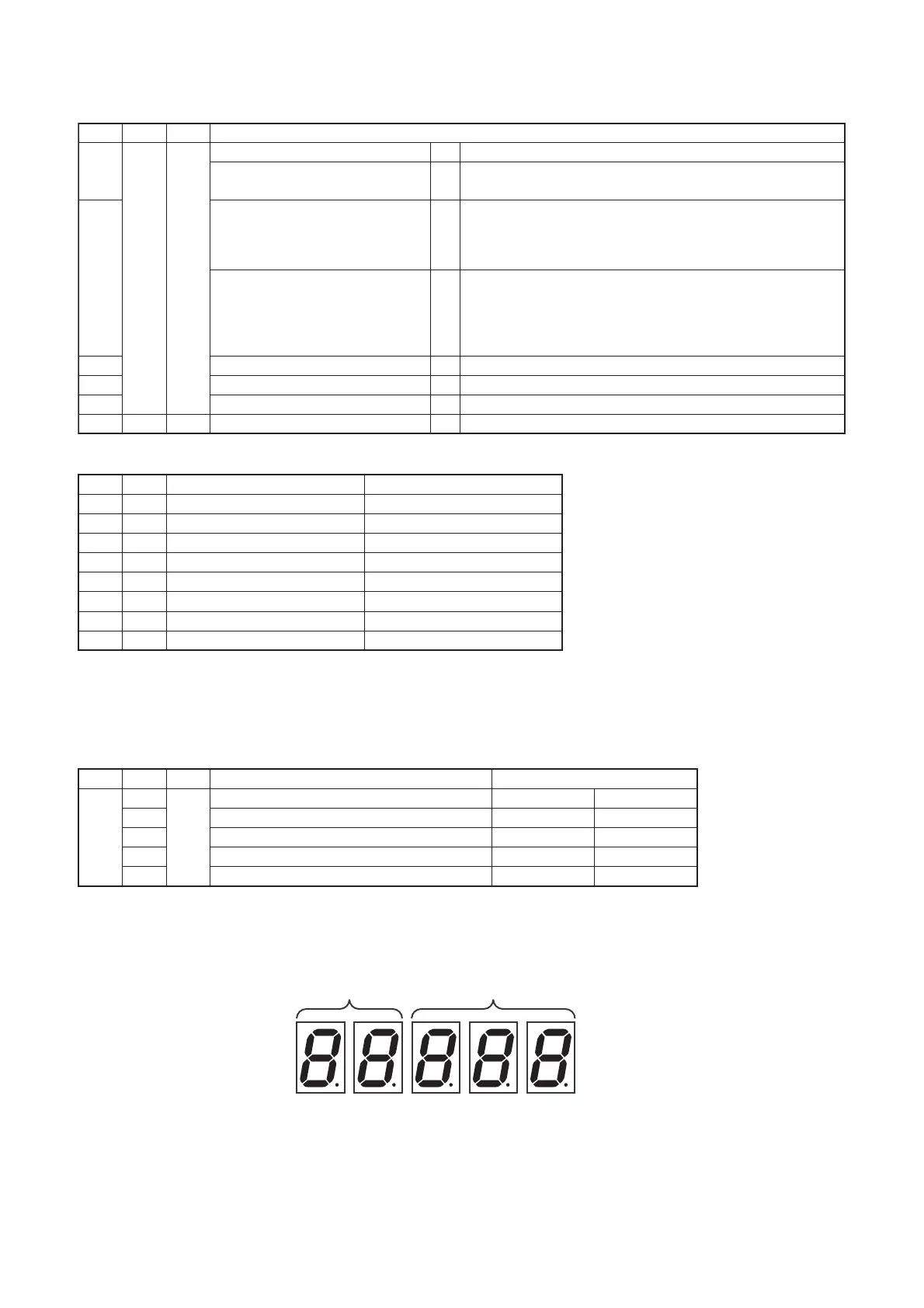
Explains the function and usage of the 7-segment display.

8-7. Oil Level Judgment Display

How to check compressor oil levels using the display.

8-8. SMMS-u Outdoor Interface P.C. Board Function Setting Change Table

Table detailing DIP switch and function settings.

8-9. Leakage/Clogging of Refrigerating Cycle Circuit

Identifies check codes related to refrigerant or oil circuit issues.

9. BACKUP OPERATION (EMERGENCY OPERATION)

9-1. Note for Backup Operation

Important notes and considerations for backup operations.

9-2. Compressor Backup Operation Setting

Procedure for setting compressor backup operation.

9-3. Outdoor Unit Backup Operation Setting

Procedures for setting outdoor unit backup operation.

9-4. Cooling-Season Outdoor Unit Backup Operation Setting

Specific backup operation settings for cooling season.

9-5. Outdoor Unit Automatic Backup Operation Outline

Overview of the automatic backup operation function.

10. OUTDOOR UNIT REFRIGERANT RECOVERY METHOD

10-1. Refrigerant Recovery from Troubled Outdoor Unit (Reclaim)

Methods for reclaiming refrigerant from faulty outdoor units.

10-2. How to Operate System While Troubled Outdoor Unit Being Repaired

Guides system operation while a unit is under repair.

10-3. Work procedure after Repair

Steps to follow after completing repairs, including vacuuming.

11. REPLACING COMPRESSORS

11-1. Compressor Replacement Procedure (Outline)

Outlines the general steps for compressor replacement.

11-2. Replacement of Compressors

Detailed steps for replacing compressors and adjusting oil.

11-3. Check Procedure to Search Cause of Compressor Oil Shortage

Diagnosing causes of compressor oil shortage.

12. OUTDOOR UNIT PARTS REPLACEMENT METHODS

13. P.C. BOARD REPLACEMENT PROCEDURES

13-1. Replacement of outdoor P.C. board & Inverter Parts

Lists service parts for outdoor PC boards and inverters.

14. EXPLODED DIAGRAM/PARTS LIST

14-1. Outdoor unit (8, 10, 12, 14HP)

Exploded diagram and parts list for 8-14HP outdoor units.

14-2. Outdoor unit (14A, 16, 18, 20HP)

Exploded diagram and parts list for 14A-20HP outdoor units.

14-3. Outdoor unit (22, 24HP)

Exploded diagram and parts list for 22-24HP outdoor units.

Related product manuals