EasyManua.ls Logo

Toshiba MMY-MUP2401HT8P-A User Manual

Toshiba MMY-MUP2401HT8P-A
309 pages
To Next Page IconTo Next Page
To Previous Page IconTo Previous Page
Page #295 background imageLoading...
Page #295 background image
14. EXPLODED DIAGRAM/PARTS LIST
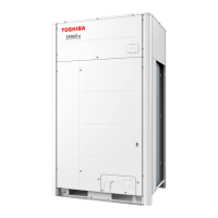
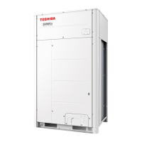
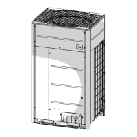
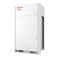
14-1. Outdoor unit (8, 10, 12, 14HP)
MMY-MUP0801*
MMY-MUP1001*
MMY-MUP1201*
MMY-MUP1401*
001
002
003
004
005
007
013
015
056 057
078
013
006
006
007
011
017
077
055
009
010
012
054
076
075
- 295 -

Table of Contents

Question and Answer IconNeed help?

Do you have a question about the Toshiba MMY-MUP2401HT8P-A and is the answer not in the manual?

Toshiba MMY-MUP2401HT8P-A Specifications

General IconGeneral
BrandToshiba
ModelMMY-MUP2401HT8P-A
CategoryAir Conditioner
LanguageEnglish

Summary

SERVICE MANUAL

SAFETY CAUTION

REFRIGERANT (R410A)

1. WIRING DIAGRAMS

2. PARTS RATING

2-1. Outdoor Unit (50Hz model: MMY-MUP***1HT8(J)P)

Lists parts and ratings for 50Hz outdoor units.

2-5. Inverter Assembly

Details components within the inverter assembly.

2-6. Parts Layout in Outdoor Unit

Visual representation of parts placement in outdoor units.

2-7. Parts Layout in Inverter Assembly

Visual representation of parts within the inverter assembly.

2-8. Outdoor (Inverter) Print Circuit Board

Explains the layout of the outdoor inverter circuit board.

3. REFRIGERANT PIPING SCHEMATIC DRAWING

4. COMBINED REFRIGERANT PIPING SYSTEM SCHEMATIC DIAGRAMS

4-1. Refrigerant Flow (Cooling)

Illustrates the refrigerant flow during cooling operation.

4-2. Refrigerant Flow (Single Defrost)

Illustrates the refrigerant flow during single defrost operation.

4-3. Refrigerant Flow (Heating)

Illustrates the refrigerant flow during heating operation.

4-4. Refrigerant Flow (Individual Defrost)

Illustrates refrigerant flow for individual defrost operations.

4-5-1. (1) Refrigerant Flow (Automatic emergency cooling)

Shows refrigerant flow during automatic emergency cooling.

4-5-2. (1) Refrigerant Flow (Automatic emergency heating)

Shows refrigerant flow during automatic emergency heating.

4-6. Refrigerant Flow (Reclaim)

Illustrates refrigerant flow during the reclaim process.

5. CONTROL OUTLINE

5-1. Outdoor Unit

Details the control functions of the outdoor unit.

6. APPLIED CONTROL AND FUNCTIONS

6-1. Optional connector Specifications of Indoor P.C.Board

Lists specifications for optional indoor P.C. board connectors.

6-2. Test Operation of Indoor Unit

Describes how to perform test operations for indoor units.

6-3. Method to Set Indoor Unit Function DN Code

Explains how to set indoor unit function codes via remote controller.

6-4. Method to set Outdoor Unit Function Code No. (O.DN )

Guides setting outdoor unit function codes using switches or remote controller.

6-5. Applied Control of Indoor Unit

Details control systems using remote location ON/OFF boxes.

6-6. Applied Control of Outdoor Unit

Explains applied controls for outdoor units based on settings.

6-7. Notice Code

Explains how notice codes are displayed and managed.

6-8. System Cooperation Defrosting

Describes how systems cooperate to manage defrosting timing.

6-9. Night operation (Sound reduction control)

Details how to set night operation for reduced sound levels.

7. TEST OPERATION

7-1. Procedure and Summary of Test Operation

Provides an overview and steps for test operations.

7-2. Check Items before Test Operation (before powering-on)

Lists essential checks before starting test operations.

7-3. Check at Main Power-on

Steps to check the system after main power is turned on.

7-4. Address Setup

Procedures for setting system addresses.

7-5. Troubleshooting in Test Operation

Addresses issues encountered during test operations.

7-6. Test Operation Check

Procedures to check system operation after test run.

7-7. Service Support Function

Provides functions for service support and troubleshooting.

7-8. Wave Tool Advance for SMMS-u Series

Information on using the Wave Tool Advance application.

8. TROUBLESHOOTING

8-1. Overview

Provides an overview of troubleshooting procedures and tools.

8-2. Troubleshooting method

Explains how to use check codes for troubleshooting.

8-3. Troubleshooting based on information displayed on remote controller

Troubleshooting based on remote controller displays and history.

8-5. Diagnosis procedure for each check code

Flowcharts for diagnosing specific check codes.

8-6. 7-Segment Display Function

Explains the function and usage of the 7-segment display.

8-7. Oil Level Judgment Display

How to check compressor oil levels using the display.

8-8. SMMS-u Outdoor Interface P.C. Board Function Setting Change Table

Table detailing DIP switch and function settings.

8-9. Leakage/Clogging of Refrigerating Cycle Circuit

Identifies check codes related to refrigerant or oil circuit issues.

9. BACKUP OPERATION (EMERGENCY OPERATION)

9-1. Note for Backup Operation

Important notes and considerations for backup operations.

9-2. Compressor Backup Operation Setting

Procedure for setting compressor backup operation.

9-3. Outdoor Unit Backup Operation Setting

Procedures for setting outdoor unit backup operation.

9-4. Cooling-Season Outdoor Unit Backup Operation Setting

Specific backup operation settings for cooling season.

9-5. Outdoor Unit Automatic Backup Operation Outline

Overview of the automatic backup operation function.

10. OUTDOOR UNIT REFRIGERANT RECOVERY METHOD

10-1. Refrigerant Recovery from Troubled Outdoor Unit (Reclaim)

Methods for reclaiming refrigerant from faulty outdoor units.

10-2. How to Operate System While Troubled Outdoor Unit Being Repaired

Guides system operation while a unit is under repair.

10-3. Work procedure after Repair

Steps to follow after completing repairs, including vacuuming.

11. REPLACING COMPRESSORS

11-1. Compressor Replacement Procedure (Outline)

Outlines the general steps for compressor replacement.

11-2. Replacement of Compressors

Detailed steps for replacing compressors and adjusting oil.

11-3. Check Procedure to Search Cause of Compressor Oil Shortage

Diagnosing causes of compressor oil shortage.

12. OUTDOOR UNIT PARTS REPLACEMENT METHODS

13. P.C. BOARD REPLACEMENT PROCEDURES

13-1. Replacement of outdoor P.C. board & Inverter Parts

Lists service parts for outdoor PC boards and inverters.

14. EXPLODED DIAGRAM/PARTS LIST

14-1. Outdoor unit (8, 10, 12, 14HP)

Exploded diagram and parts list for 8-14HP outdoor units.

14-2. Outdoor unit (14A, 16, 18, 20HP)

Exploded diagram and parts list for 14A-20HP outdoor units.

14-3. Outdoor unit (22, 24HP)

Exploded diagram and parts list for 22-24HP outdoor units.

Related product manuals