(8) Screw the Fan-motor P.C. board to the heat sink by the two screws (
e
) that were removed in step (3).
If the screws are loose, the semiconductors will generate heat, and cause it to breakdown.
Do not use an electric driver or an air driver.
The semiconductor may receive a damage.
The torque of the screws
Screw
M314 0.6N• m
MCC-1748 : 1pcs
Spacer : 4pcs
Spacer : 2pcs
Bush : 6pcs
%0
%0
%0
%0
6
.
..
4'& 9*+ $.-
%0 %0 %0
4'&
9*+ $.-
%0
%0 %0
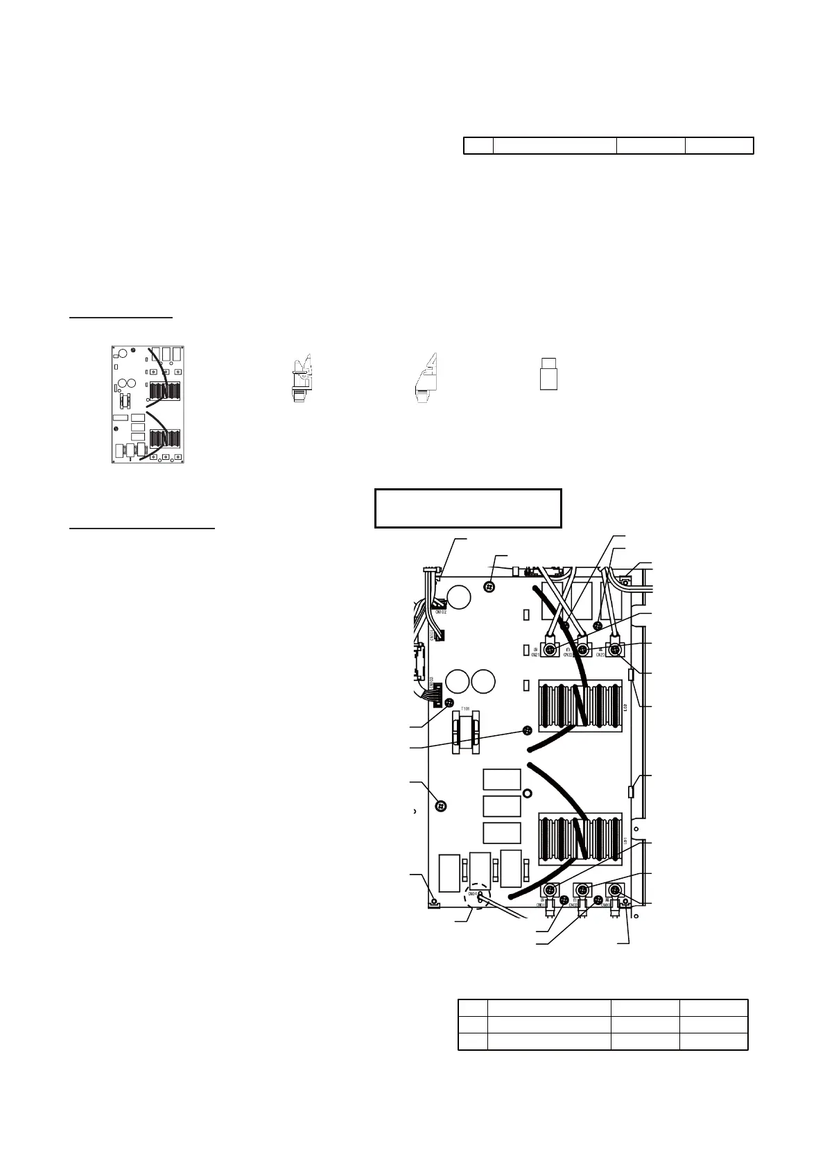
Noise Filter P.C. board
(43T6W888)
Spacer
Space r
Spacer
Spacer
Spacer
Spacer
WHITE lead wire
CN02
BLACK lead wire
CN03
RED lead wire
CN01
Screw
Screw
Screw
Screw
Screw
Screw
Screw
Screw
Solderless terminal
(CN04)
WHITE lead wire
CN22
BLACK lead wire
CN23
RED lead wire
CN21
The torque of the screws
Screw
M3 × 18 0.6N• m
Screw
M4 × 8 1.2N• m
Screw terminals
M6 × 12
2.5N• m
(9) Re-connect the connectors. Be sure that all the connectors are connected correctly and securely inserted.
(10) If the components on the P.C. board were bent during board replacement, adjust it manually ensuring that
it is not short-circuited or contact other parts.
(11) Install the cover, then turn on the supply. Check the operation.
13-1-6. Noise Filter P.C. Board 1 (MCC-1748) Replacement Procedure
Subject part 43T6W888: MMY-MUP0801*/1001*/1201*/1401*
Included item:
Replacement Steps:
(1) Turn off the power supply of the outdoor
unit and wait at least 5 minutes for the
capacitor to discharge.
(2) Remove all of the connector and
solderless terminal tab (CN04), screw
terminal (
i
: 6pcs) which were
connected to the Noise Filter P.C.
board.
Solderless terminal tab need to push
lock pin. (Remove the connectors by
pulling the connector body. Do not pull
the wire.)
(3) Remove eight screws
(
g
: 6pcs,
h
: 2pcs).
(These screws are to be re-used after
procedure.)
(4) Remove the P.C. board from the four
spacers (
d
: 4pcs,
e
: 2pcs).
(5) Using a new spacer (
d
,
e
), a bush
(
f
), attach the service board.
(6) Screw the Noise Filter P.C. board by the
eight screws (
g
,
h
) that were
removed in step (3).
(7)
(10
) If the components on the P.C.board
were bent during board replacement,
adjust it manually ensuring that it is
not short-circuited or contact other
parts.
Re-connect the connectors and screw
terminals (
i
), solderless terminal tab
(CN04).
Be sure that all the connectors and the
screw terminals are connected correctly
and securely inserted.
(11) Install the cover, then turn on the
supply. Check the operation.
 Loading...