1.2 Names and Functions of the Parts
Unified Controller nv series PROFIBUS(PA912) Module Instruction Manual
9
1.2 Names and Functions of the Parts
1.2.1 Names of the parts
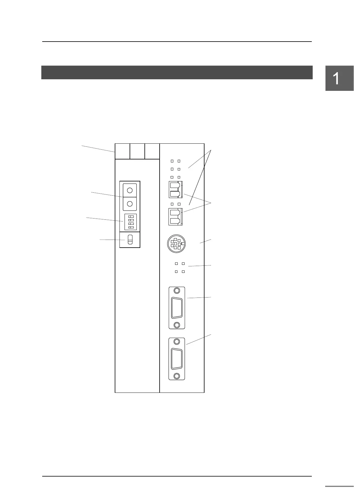
Figure 1-6 shows the names of the parts of the PA912 module and I/O base unit
BU90A.
Figure 1-6 Names of the parts of the PA912 module and I/O base unit
BU90A
net I/O loop state display LED
TC-net I/O loop connector
Serial communication port
・TOOL
PROFIBUS transmission connector
PROFIBUS configurator
tool port
・ RUN
・ ERR
・ LP
・ SCAN
・ ACT1
・ ACT2
・ LNK1
・ LNK2
・PROFIBUS-DP
・CONFIG
PROFIBU State display LED
・CFG
・MODE
・COM
・TOK
・LP1 ・LP2
TC-net I/O
Loop address
setting switch
・MAINT
・STN-H ・STN-L
Operation mode
setting switch
・MODE
Maintenance switch
MODE
STN-H
STN-L
MAINT
↓RUN
PA912
LP1
LP2
TOOL
CONFIG
PROFIBUS-DP
24V
0V
FG
1 2 3
Power terminal
BU90A PA912
 Loading...


