Chapter 2 Installation and Wiring
6F8C1259
2.2.2 Horizontal installation of the module
CAUTION
Do not insert or remove any cables, and do
not install, remove
, or replace the base unit
while the power is on.
It may cause an electric shock or malfunction.
Prohibited
CAUTION
In the case of the horizontal installation,
allow a space of 50mm or more from the top
and bottom of the base unit BU90A
the PA912 is installed for ventilation.
If ventilation is insufficient, the internal
temperature of the PA912 may increase, causing
failure or malfunction.
Mandatory
PA912 can be installed in the horizontal direction.
The installation procedure is as follows.
1
Place the base unit BU90A with its power terminal is on the left side,
and its switches are on the down side.
The horizontal installation of the other positioning is not available.
2
Allow a space of 50mm or more from the top and bottom of the base
unit.
The space of the top is for the heat dissipation and the space of the bottom
is for the cables.
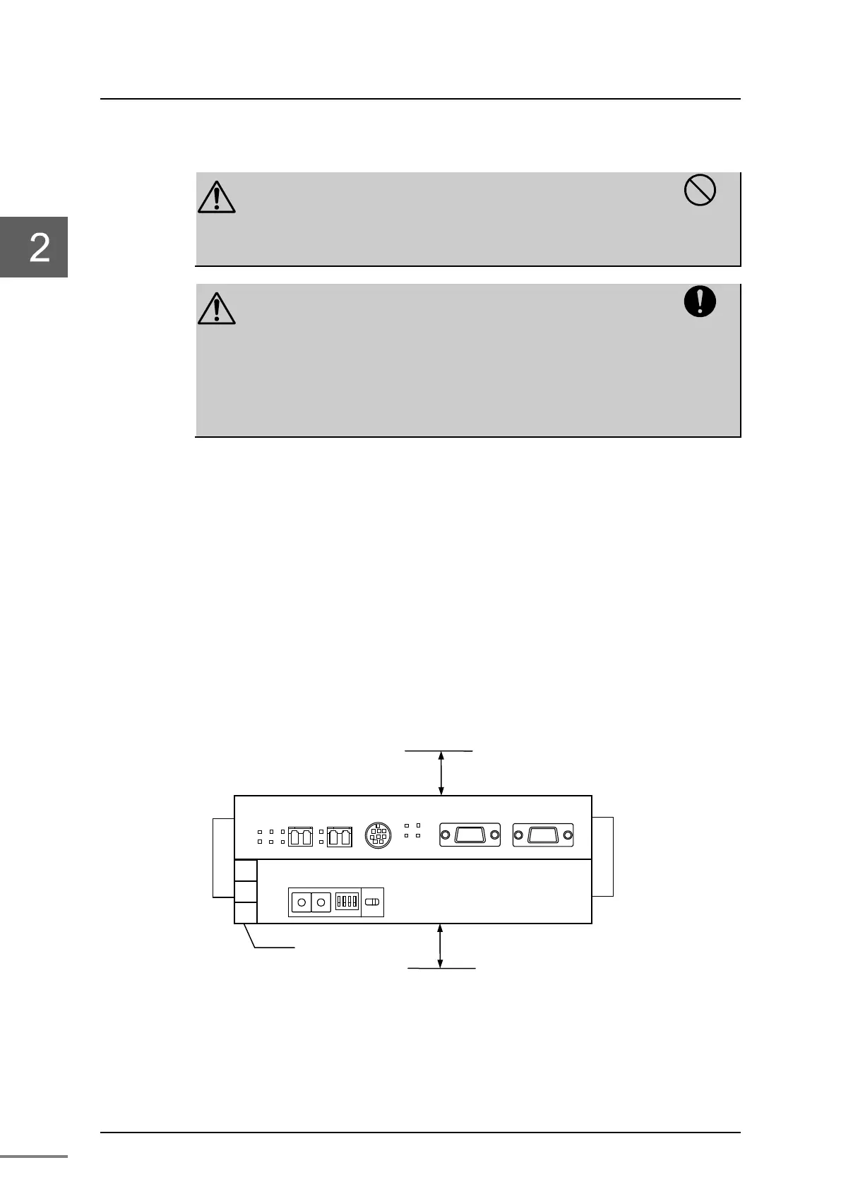
Figure 2-4 Horizontal installation
-H
-L
PA912
LP
LNK2
TOK MODE
CONFIG
PROFIBUS-DP
24V
0V FG
1 2 3
BU90A power
terminal
50mm or more
 Loading...


