2.3 Connecting the TC-net I/O Loop Transmission Connector
Unified Controller nv series PROFIBUS(PA912) Module Instruction Manual
21
2.3
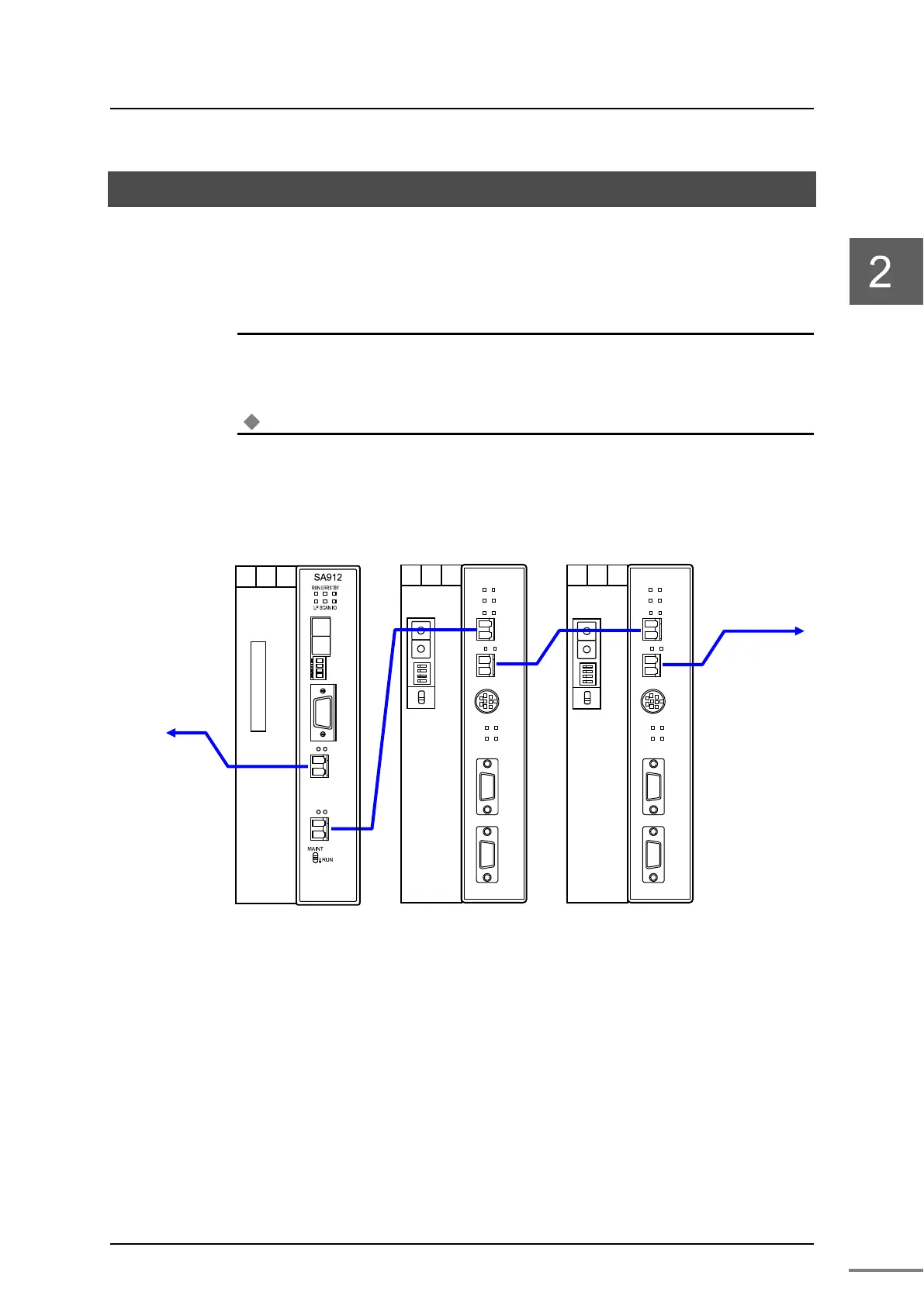
Connecting the TC-net I/O Loop Transmission Connector
Connect the TC-net I/O loop transmission cable.
Figure 2-5 and Figure 2-6 show the order of connection of the cables.
◆
◆◆
◆
Important
・
Connect the cable correctly, otherwise I/O loop status may not be displayed “normal” on the
system view screen of the nV-Tool.
Note
•
Use an optical transmission cable (double-LC connector, core diameter/cladding diameter:
50/125, 62.5/125) as a transmission cable connected to the TC-net I/O loop.
For the handling suggestions of optical transmission cable, refer to "Unified Controller nv
series High-Speed Serial I/O System TC-net I/O Instruction Manual" (6F8C1240).
Figure 2-5 TC-net I/O loop transmission cable connection
(optical cables only)
24V
0V
FG
1 2 3
PA912
ERR
RUN
SCAN
LP
ACT2
LNK2
LP1
LP2
TOOL
COM
CFG
TOK
CONFIG PROFIBUS-DP
ACT1
LNK1
MODE
STN-H
STN-L
MAINT
↓RUN
24V
0V
FG
1 2 3
PA912
ERR
RUN
SCAN
LP
ACT2
LNK2
LP1
LP2
TOOL
COM
CFG
TOK
CONFIG PROFIBUS-DP
ACT1
LNK1
to the
latter LP1
from the
former LP2
ACT2
LNK2
LNK1
ACT1
24V
0V
FG
1 2 3
MODE
STN-H
STN-L
MAINT
↓RUN
 Loading...


