2.4 Connecting the PROFIBUS Transmission Connectors
Unified Controller nv series PROFIBUS(PA912) Module Instruction Manual
23
2.4 Connecting the PROFIBUS Transmission Connectors
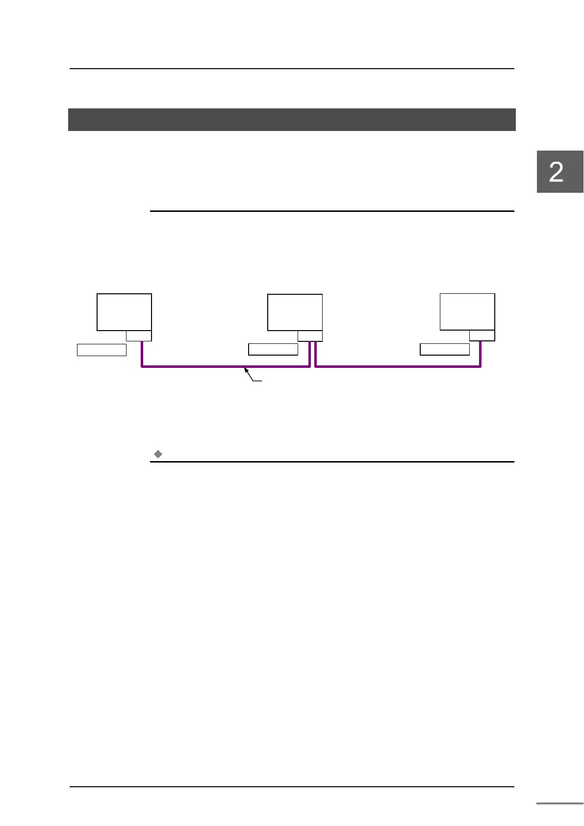
The PROFIBUS transmission cables are connected between the connectors in
the order illustrated in Figure 2-7.
◆
◆◆
◆
Important
・
At terminating stations, turn ON the termination resistor "TERM" built in the connectors.
Figure 2-7 Connection of PROFIBUS transmission cables
Note
For information on twisted pair cable and the connector for the PROFIBUS, refer to
"Appendix C Related Products."
Slave
(
Terminating station
)
(
Terminating station
)
Twisted pair cable
Slave
Connector
TERM=ON
PA912
Connector
TERM=OFF
Connector
TERM=ON