TMC7 SERIES
TMC7 Series
Page 12
710-02887-00A
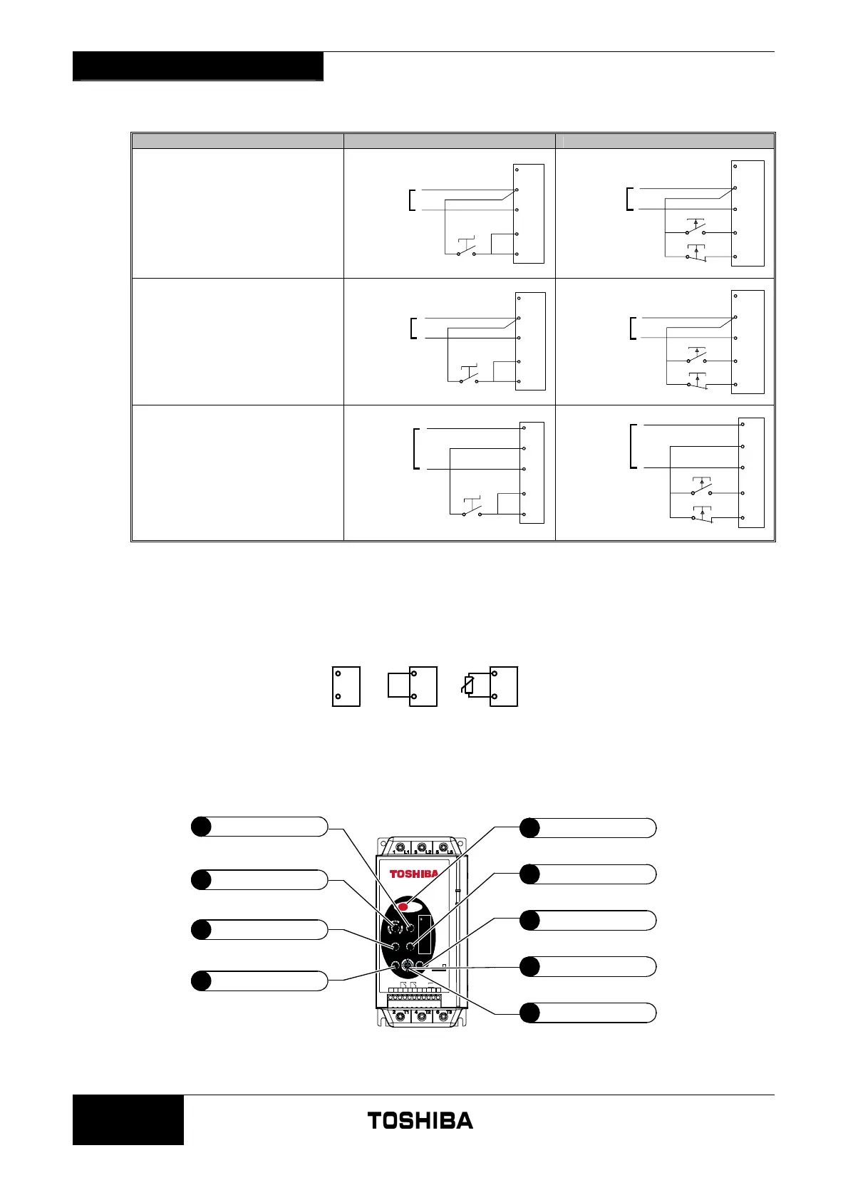
4.4 Control Circuits
Control Voltage 2 Wire Control 3 Wire Control
24 VAC/VDC (C2 models)
24 VAC/VDC
(+)
(-)
A3
A1
A2
01
02
START/
STOP
*
24 VAC/VDC
(+)
(-)
A3
A1
A2
01
02
START
STOP
*
110-240 VAC (C1 models)
110-240 VAC
(+)
(-)
A3
A1
A2
01
02
START/
STOP
*
110-240 VAC
(+)
(-)
A3
A1
A2
01
02
START
STOP
*
380-440 VAC (C1 models)
A3
A1
A2
01
02
START/
STOP
*
380-440 VAC
380-440 VAC
A3
A1
A2
01
02
START
STOP
*
* Also resets trip states.
4.5 Motor Thermistor
Motor thermistors (if any) can be connected directly to the TMC7 terminals C1 & C2. If no motor thermistors are connected there must
be a link between C1 & C2.
C1
C2
C1
C2
C1
C2
989
4.6 Adjustments
Ready
Run
TOSH IBA INT ERNA TIONA L CO RP ORA TIO N PT Y LTD - AU STRA LIA
SOFT S TARTER
C1 R33 R34C2 R43R44 02
01 A2 A1 A3
Motor
Therm istor
Input N.O. N.O.
Relay Outputs
110 - 24 0V AC
Control Supply
380 - 440VAC or
StartSto p
RESET
Aux
Rel ay
Phase
Rotation
TRIP CODES
Ready
x 1. Po wer
C ircu it
x 2. Excess
S tar t Ti me
x 3. Motor
Overload
x 4. Motor
Ther mistor
x 5. Current
Imbalance
x 6. Supply
F requency
x 7. Phase
R ota tion
x 8. Com ms
F ail ure
Motor FLC
(% TMC7 FLC)
Current Ramp
(%FLC/Ramp Time)
OFF
5s
15s
15
2s
5s5s
2s
2s
15
70%
80%
60% 90%
100%
50%
Curre nt Lim it
(% Motor FLC)
350 %
450%
400%300 %
250%
Motor Trip
Class
OFF
2
4
6
8
10
12
14
16
20
Excess
Start Time
OFF
2s
4s
6s
8s
10s
12s
14s
16s
20s
TMC
7
SERIES
Soft Stop
(Seconds)
No
Soft Stop
2s
4s
6s
8s
10s
12s
14s
16s
20s
2
3
4
1
Motor Full Load Current
Current Ramp
Current Limit
Motor Trip Class
5
Local Reset Push Button
6
Soft Stop Time
7
Excess Start Time
8
Phase Rotation Protection
9
Auxiliary Relay Function
 Loading...


