44
E6582383
SW1SW2
RES
S1 S2
VIA
PP
VIB CC VIC S3 FM
NO
CC
OUT
P24
F
R CC
+SU
STO
FLA FLB FLC RY RC
Bไᚚᅇ㊰➃ᏊྎB-HSV
Screw size
Recommended
tightening torque
M3 screw
0.5 Nm
4.4 lbin
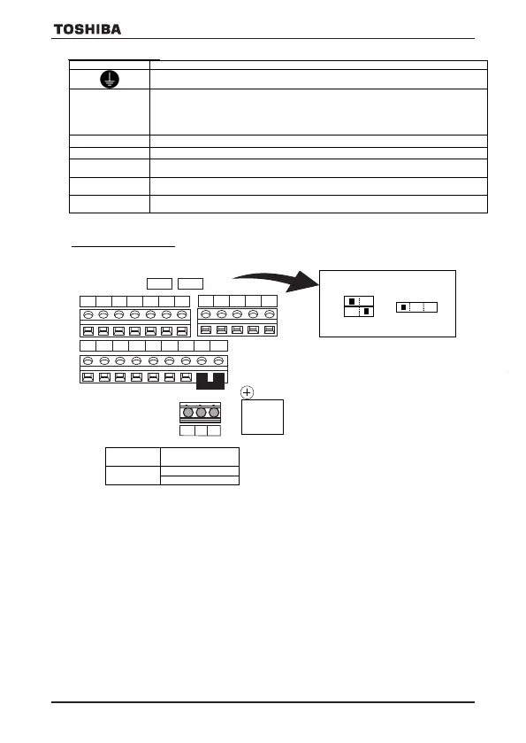
RS485 connector
Stripping length: 6 (mm)
Screwdriver: Small-sized flat-blade screwdriver
(Blade thickness: 0.5 mm, blade width: 3.5 mm)
Screw for removable control terminal block
SINK
SOURCE
PLC
VIB
SW2
PTC
S3
S4
Main circuit terminals
Terminal symbol Terminal function
Grounding terminal for connecting inverter. There are 3 terminals in cooling fin or mounting part of
EMC plate.
R/L1,S/L2,T/L3
200/240 V class : Three-phase 200 to 240V-50/60Hz
: Single-phase 200 to 240V-50/60Hz
400/500 V class : Three-phase 380 to 480V(UL)-50/60Hz
600V class : Three-phase 525 to 600V-50/60Hz
inputs are R/L1 and S/L2/N terminals.
U/T1,V/T2,W/T3
Connect to three-phase motor.
PA/+, PB
Connect to braking resistors.
PA/+
This is a positive potential terminal in the internal DC main circuit.
DC common power can be input between PA/+ terminal and PC/- terminal.
PC/-
This is a negative potential terminal in the internal DC main circuit.
DC common power can be input between PC/- terminal and PA/+ terminal.
PO, PA/+
Terminals for connecting a DC reactor (DCL: optional external device). Shorted by a
shorting bar when shipped from the factory. Before installing DCL, remove the shorting bar.
The arrangements of power circuit terminals are different from each range.
Control circuit terminals
The control circuit terminal block is common to all equipment.
E6582383
10
Terminal
symbol
output
Function
Electrical
specifications
F Input
Multifunction programmable logic input
Shorting across F-CC or P24-F causes forward rotation; open
causes deceleration stop.
(When Standby ST is always ON)
3 different functions can be assigned.
No voltage
logic input
24Vdc-5mA or
less
Sink/Source and
PLC selectable
using slide switch
SW1
(Default setting is
Sink side)
Pulse train input
(S2 terminal)
Pulse frequency
range:
10pps~2kpps
Duty: 50±10%
PTC input
(S3 terminal)
R Input
Shorting across R-CC or P24-R causes reverse rotation; open
causes deceleration stop.
(When Standby ST is always ON)
3 different functions can be assigned.
RES Input
This inverter protective function is reset if RES-CC or P24-RES is
connected. Shorting RES-CC or P24-RES has no effect when the
inverter is in a normal condition.
2 different functions can be assigned.
S1 Input
Shorting across S1-CC or P24-S1 causes preset speed operation.
2 different functions can be assigned.
S2 Input
Shorting across S2-CC or P24-S2 causes preset speed operation.
By changing parameter f146 setting, this terminal can also be
used as a pulse train input terminal.
S3 Input
Shorting across S3-CC or P24-S3 causes preset speed operation.
By changing slide switch SW2 and parameter f147 setting, this
terminal can also be used as a PTC input terminal.
CC
Common
to Input /
Control circuit's equipotential terminal (3 terminals) -
PP Output Analog power supply output
10Vdc
(permissible load
Input
Multifunction programmable analog input.
Default setting: 0-10Vdc (1/1000 resolution) and 0-60Hz (0-50Hz)
frequency input.
By changing parameter f109, this terminal can also be used as a
ultifunction programmable logic input terminal.
10Vdc
(internal
impedance: 30kΩ)
Input
Multifunction programmable analog input.
Default setting: 0-10Vdc (1/1000 resolution) and 0-60Hz (0-50Hz)
frequency input.
The function can be changed to -10-+10V input (1/2000 resolution) by
parameter f107 =1 setting.
By switching slide switch SW2 and changing parameter f109 setting,
this terminal can also be used as a multifunction programmable logic
10Vdc
(internal
impedance: 30kΩ)
V I C Input
Multifunction programmable analog input.
4-20mA (0-20mA) input.
4-20mA
(internal
impedance: 250Ω)
FM Output
Multifunction programmable analog output. Default setting: output
frequency.
The function can be changed to meter option (0-1mA), 0-10Vdc voltage
or 0-20mAdc (4-20mA) current output by parameter f681 setting.
Resolution Max. 1/1000.
1mAdc full-scale
ammeter or
QS6T(option)
0-20mA (4-20mA)
DC ammeter
Permissible load
resistance:
600Ω or less
0-10V DC volt
meter
Permissible load
resistance:
VF-S15_QS.indb 44VF-S15_QS.indb 44 2021/11/18 15:51:542021/11/18 15:51:54
SW1SW2
RES
S1 S2
VIA
PP
VIB CC VIC S3 FM
NO
CC
OUT
P24
F
R CC
+SU
STO
FLA FLB FLC RY RC
Bไᚚᅇ㊰➃ᏊྎB-HSV
Recommended
tightening torque
M3 screw
0.5 Nm
4.4 lbin
RS485 connector
Stripping length: 6 (mm)
Screwdriver: Small-sized flat-blade screwdriver
(Blade thickness: 0.5 mm, blade width: 3.5 mm)
Screw for removable control terminal block
SINK
VIB
SW2
PTC
S3
S4
Main circuit terminals
Terminal symbol Terminal function
Grounding terminal for connecting inverter. There are 3 terminals in cooling fin or mounting part of
EMC plate.
R/L1,S/L2,T/L3
200/240 V class : Three-phase 200 to 240V-50/60Hz
: Single-phase 200 to 240V-50/60Hz
400/500 V class : Three-phase 380 to 480V(UL)-50/60Hz
600V class : Three-phase 525 to 600V-50/60Hz
inputs are R/L1 and S/L2/N terminals.
U/T1,V/T2,W/T3
Connect to three-phase motor.
PA/+, PB
Connect to braking resistors.
PA/+
This is a positive potential terminal in the internal DC main circuit.
DC common power can be input between PA/+ terminal and PC/- terminal.
PC/-
This is a negative potential terminal in the internal DC main circuit.
DC common power can be input between PC/- terminal and PA/+ terminal.
PO, PA/+
Terminals for connecting a DC reactor (DCL: optional external device). Shorted by a
shorting bar when shipped from the factory. Before installing DCL, remove the shorting bar.
The arrangements of power circuit terminals are different from each range.
Control circuit terminals
The control circuit terminal block is common to all equipment.
output
Function
Electrical
specifications
F Input
Multifunction programmable logic input
Shorting across F-CC or P24-F causes forward rotation; open
causes deceleration stop.
(When Standby ST is always ON)
3 different functions can be assigned.
No voltage
logic input
24Vdc-5mA or
less
Sink/Source and
PLC selectable
using slide switch
SW1
(Default setting is
Sink side)
Pulse train input
(S2 terminal)
Pulse frequency
range:
10pps~2kpps
Duty: 50±10%
PTC input
(S3 terminal)
R Input
Shorting across R-CC or P24-R causes reverse rotation; open
causes deceleration stop.
(When Standby ST is always ON)
3 different functions can be assigned.
RES Input
This inverter protective function is reset if RES-CC or P24-RES is
connected. Shorting RES-CC or P24-RES has no effect when the
inverter is in a normal condition.
2 different functions can be assigned.
S1 Input
Shorting across S1-CC or P24-S1 causes preset speed operation.
2 different functions can be assigned.
S2 Input
Shorting across S2-CC or P24-S2 causes preset speed operation.
By changing parameter f146 setting, this terminal can also be
used as a pulse train input terminal.
S3 Input
Shorting across S3-CC or P24-S3 causes preset speed operation.
By changing slide switch SW2 and parameter f147 setting, this
terminal can also be used as a PTC input terminal.
CC
Common
to Input /
Control circuit's equipotential terminal (3 terminals) -
PP Output Analog power supply output
10Vdc
(permissible load
Input
Multifunction programmable analog input.
Default setting: 0-10Vdc (1/1000 resolution) and 0-60Hz (0-50Hz)
frequency input.
By changing parameter f109, this terminal can also be used as a
ultifunction programmable logic input terminal.
10Vdc
(internal
impedance: 30kΩ)
Input
Multifunction programmable analog input.
Default setting: 0-10Vdc (1/1000 resolution) and 0-60Hz (0-50Hz)
frequency input.
The function can be changed to -10-+10V input (1/2000 resolution) by
parameter f107 =1 setting.
By switching slide switch SW2 and changing parameter f109 setting,
this terminal can also be used as a multifunction programmable logic
10Vdc
(internal
impedance: 30kΩ)
V I C Input
Multifunction programmable analog input.
4-20mA (0-20mA) input.
4-20mA
(internal
impedance: 250Ω)
FM Output
Multifunction programmable analog output. Default setting: output
frequency.
The function can be changed to meter option (0-1mA), 0-10Vdc voltage
or 0-20mAdc (4-20mA) current output by parameter f681 setting.
Resolution Max. 1/1000.
1mAdc full-scale
ammeter or
QS6T(option)
0-20mA (4-20mA)
DC ammeter
Permissible load
resistance:
600Ω or less
0-10V DC volt
meter
Permissible load
resistance:
VF-S15_QS.indb 45VF-S15_QS.indb 45 2021/11/18 15:51:552021/11/18 15:51:55
VF-S15_QS_CC2021.indd 44VF-S15_QS_CC2021.indd 44 2021/11/18 15:55:322021/11/18 15:55:32
 Loading...