50
E6582383
S3
PTC
CC
5) Overload alarm level
f
6
5
7
When the motor overload level reaches to f657 setting value (%) of overload trip (ol2) level, “l” will be displayed
on the left side digit and the “l” and output frequency monitor will be blinking alternately on overload alarm status.
Overload alarm signal can be output from output terminal.
6. Motor PTC thermal protection
Set a parameter f147 and lower slide switch of SW2 to PTC side, when S3 terminal is used as PTC input terminal.
f147 : Logic input / PTC input selection (S3)
f645 : PTC thermal selection
f646 : Resistor value for PTC detection
• Function
This function is used to protect motor from overheating using the signal of PTC built-in motor.
The trip display is “e-32”.
[Parameter setting]
Title Function Adjustment range Default setting
f147
Logic input / PTC input selection (S3)
0: Logic input
1: PTC input
0
f645 PTC thermal selection
1: Tripping
2: Alarm only
1
f646 PTC detection resistor value 100-9999 (Ω) 3000
Note : Protecting PTC thermal, set f147=1 (PTC input) and slide switch SW2 to PTC side.
● Tripping level is defined by f646 setting. Alarm level is defined by 60% of f646 setting.
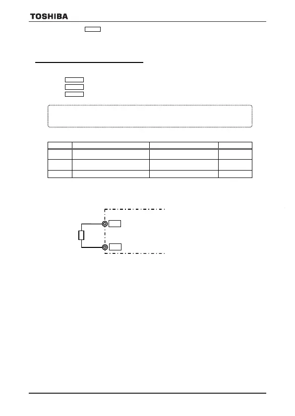
● Connect the PTC between S3 and CC terminals. Detection temperature can be set by f646 setting.
[Connection]
● Output of PTC input alarm signal
The PTC input alarm is assigned to the output terminal by setting the parameter of the output terminal selection
function to 150 or 151.
Operation of this equipment requires detailed installation and operation
instructions provided in the hardware manual intended for use with this
product.
This information is provided on the CD-ROM included in the container
this device was packaged in.
This information should be retained with this device at all times.
Please contact where you purchase the inverter, your Toshiba sales representative, if
you need the hard copy (paper) of CD-ROM. Or please contact to phone number of
back cover in E6581610(Japanese), E6581612(Japanese), E6582175(English) or
E6581928(English).
© Toshiba Schneider Inverter Corporation 2020
VF-S15_QS.indb 50VF-S15_QS.indb 50 2021/11/18 15:51:562021/11/18 15:51:56
5) Overload alarm level
ff665577
When the motor overload level reaches to f657 setting value (%) of overload trip (ol2) level, “l” will be displayed
on the left side digit and the “l” and output frequency monitor will be blinking alternately on overload alarm status.
Overload alarm signal can be output from output terminal.
6. Motor PTC thermal protection
Set a parameter f147 and lower slide switch of SW2 to PTC side, when S3 terminal is used as PTC input terminal.
f147 : Logic input / PTC input selection (S3)
f645 : PTC thermal selection
f646 : Resistor value for PTC detection
• Function
This function is used to protect motor from overheating using the signal of PTC built-in motor.
The trip display is “e-32”.
[Parameter setting]
Title Function Adjustment range Default setting
Logic input / PTC input selection (S3)
0: Logic input
1: PTC input
0
f645 PTC thermal selection
1: Tripping
2: Alarm only
1
f646 PTC detection resistor value 100-9999 (Ω) 3000
Note : Protecting PTC thermal, set f147=1 (PTC input) and slide switch SW2 to PTC side.
● Tripping level is defined by f646 setting. Alarm level is defined by 60% of f646 setting.
● Connect the PTC between S3 and CC terminals. Detection temperature can be set by f646 setting.
[Connection]
● Output of PTC input alarm signal
The PTC input alarm is assigned to the output terminal by setting the parameter of the output terminal selection
function to 150 or 151.
Operation of this equipment requires detailed installation and operation
instructions provided in the hardware manual intended for use with this
product.
This information is provided on the CD-ROM included in the container
this device was packaged in.
This information should be retained with this device at all times.
Please contact where you purchase the inverter, your Toshiba sales representative, if
you need the hard copy (paper) of CD-ROM. Or please contact to phone number of
back cover in E6581610(Japanese), E6581612(Japanese), E6582175(English) or
E6581928(English).
© Toshiba Schneider Inverter Corporation 2020
VF-S15_QS.indb 51VF-S15_QS.indb 51 2021/11/18 15:51:572021/11/18 15:51:57
VF-S15_QS_CC2021.indd 50VF-S15_QS_CC2021.indd 50 2021/11/18 15:55:342021/11/18 15:55:34
 Loading...