EN
6
E6581929
Screw size Tightening torque
M3.5 screw 1.0 N·m 8.9 lb·in
M4 screw 1.4 N·m 12.4 lb·in
M5 screw 2.4 N·m 20.8 lb·in
M6 screw 4.5 N·m 40.0 lb·in
M4 screw
(grounding
terminal)
1.4 N·m 12.4 lb·in
M5 screw
(grounding
terminal)
2.8 N·m 24.8 lb·in
Voltage
class
Applicable
motor
(kW)
Wire size (mm
2
)
Power circuit Note 1)
Grounding
cable
Input
Output
without
DCL
With
DCL
3-phase
240V
0.2-1.5 1.5 1.5 1.5 2.5
2.2 2.5 1.5 1.5 2.5
4.0 4.0 2.5 2.5 4.0
5.5 10 4.0 6.0 10
7.5 16 6.0 10 16
11 25 10 16 16
15 35 16 25 16
1-phase
240V
0.2-0.75 1.5 1.5 1.5 2.5
1.5 2.5 2.5 1.5 2.5
2.2 4.0 4.0 1.5 4.0
3-phase
500V
0.4-2.2 1.5 1.5 1.5 2.5
4.0 2.5 1.5 1.5 2.5
5.5 4.0 1.5 2.5 4.0
7.5 6.0 2.5 2.5 6.0
11 10 4.0 6.0 10
15 16 6.0 10 16
Note 1) The power circuit wire length is assumed to be 30m or less.
5. Turn on the power supply
Set the setup menu after power on.
6. Operate the inverter
Panel operation is possible with default settings.
Caution
If incorrect setting, the drive may have some damage or unexpected
movement. Be sure to set the setup menu correctly.
Setting dial LED display Operation
“set”
Power on
eu
asia
jp
usa
Turn the setting dial and select region.
init
Press the setting dial
0.0
Finish setup
Parameter setting
eu a si a usa jp
Main region Europe Asia, Oceania North America Japan
Motor
230/400(V) 230/400(V) 230/460(V) 200/400(V)
50(Hz) 50(Hz) 60(Hz) 60(Hz)
Note) When you operate the inverter with external signals, please select Sink logic, Source logic, or
PLC(external power supply) by SW1.
Frequency (speed)
can be changed
with the dial.
Starts with RUN key, and
stops with STOP key.
VF-S15_QS.indb 6VF-S15_QS.indb 6 2021/11/18 15:51:372021/11/18 15:51:37
EN
7
E6581929
F
CC
R
F
P24
R
SW2
PTC
VIB
SOURCE
SINK
S3
S4
PLC
SW1
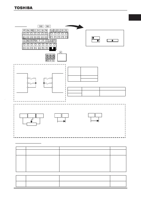
7. Operate the inverter with external signals
Wire the control circuit, set the parameter and select SW1.
7.1 Wiring
7.2 Parameter setting
Determine the operation method with cmod and frequency setting with fmod.
Select the signal of terminal VIA and VIB
Screw for removable control terminal block
RS485 connector
Initial position
Operation command
Forward run when F-CC or P24-F is ON.
<Sink logic> <Source logic>
F: Forward run command
R: Reverse run command
Screw size
Recommended
tightening
torque
M3 screw
0.5 N·m
4.4 lb·in
Stripping length: 6 (mm)
Screwdriver:
Small-sized flat-blade
type
(Blade thickness: 0.5 mm,
blade width: 3.5 mm)
Conductor 1 wire 2 wires of same size
Solid
0.3-1.5mm
2
(AWG 22-16)
0.3-0.75mm
2
(AWG 22-18)
Stranded
Frequency setting
VIA
CC PP
1)Potentiometer
fmod=1
f1 0 9 =0 or 1
(Analog)
CC VIB
- +
3) Voltage input (0 to 10V) or (-10 to +10V)
SW2: VIB
fmod=2
f1 0 7 =0 (0-+10V), 1 (-10-+10V)
f1 0 9 =0 (Analog)
CC VIC
- +
2) Current input (4 to 20mA)
fmod=8
Title Function Adjustment range Default setting
cmod
Command mode selection
0: Terminal block, 1: Panel
2: RS485, 3: CANopen, 4: Option
1
fmod
Frequency setting mode
selection 1
0: Setting dial 1, 1: Terminal VIA
2: Terminal VIB, 3: Setting dial 2
4: RS485, 5: UP/DOWN from logic input
6: CANopen, 7: Communication option
8: Terminal VIC
11: Pulse train input, 14: sro
0
f1 0 7
Analog input terminal selection
(VIB)
0: 0-+10V, 1: -10-+10V 0
f1 0 9
Analog/logic input selection
(VIA/VIB)
0 to 4 *See the instruction manual for detail. 0
VF-S15_QS.indb 7VF-S15_QS.indb 7 2021/11/18 15:51:372021/11/18 15:51:37
VF-S15_QS_CC2021.indd 7VF-S15_QS_CC2021.indd 7 2021/11/18 15:55:102021/11/18 15:55:10
 Loading...