1-29
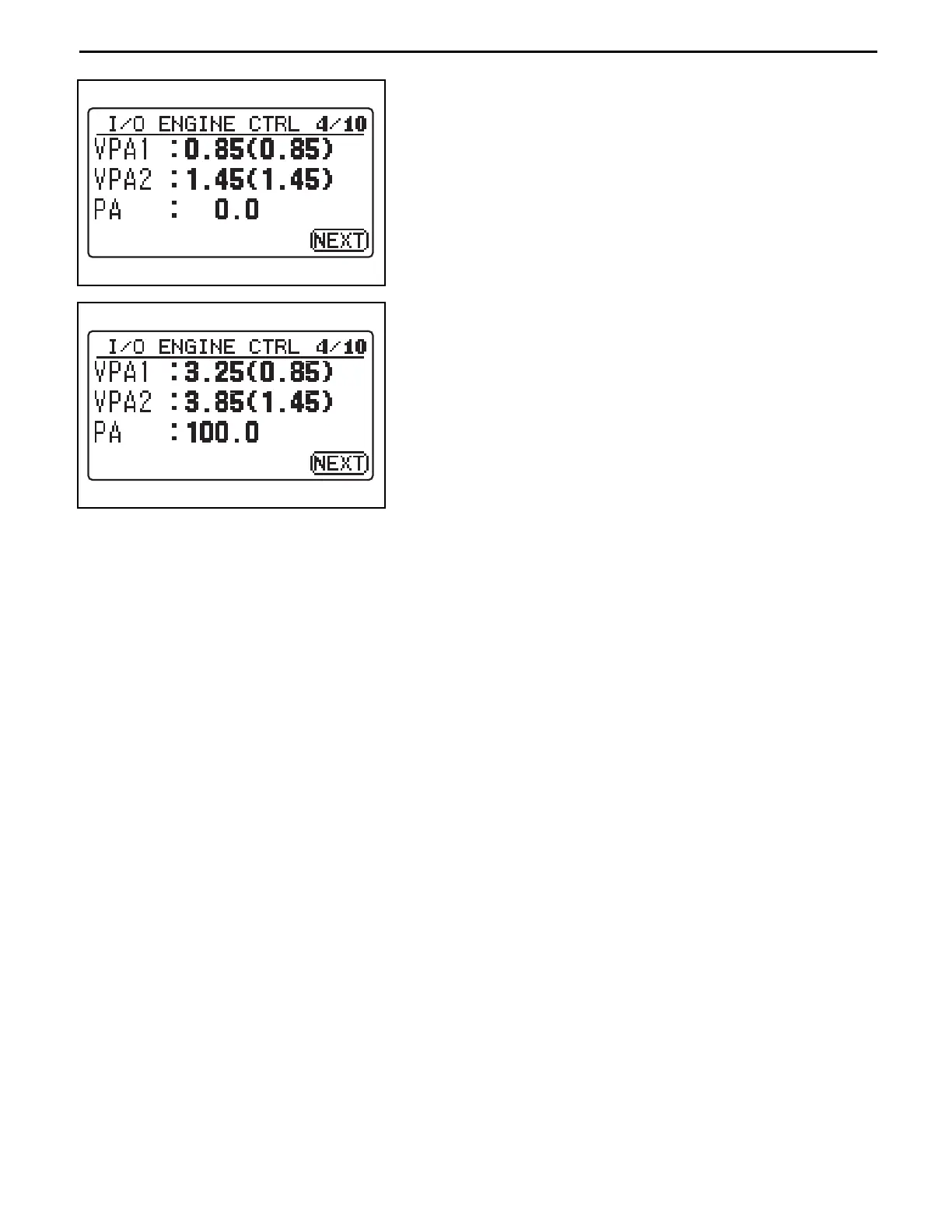
(2) Adjust the sensor voltage when the accelerator is OFF.
Display the I/O ENGINE CTRL 4/10 screen on the display.
Adjust the installation position of the accelerator sensor
so that the VPA1 output (V) comes to the value below,
and fix it with a the set screw.
VPA1: 0.85 ± 0.1 V
(3) Adjust the height of the stopper bolt so that the difference
between the VPA1 output (V) in the full throttle position
and the initial VPA1 output (V) is 2.4 V or greater, and the
VPA2 output (V) in the full throttle position is less than 4.6
V.
(Note: the change in output per single turn of the stopper
bolt is 0.06 V)
(4) After adjustment, apply thread tightener (08833-76002-71
(08833-00080)) to the threaded section of the stopper bolt
lock nut and reassemble it.
(5) Clear the learned values.
For the 4Y:
Remove the battery plug for more than 10 seconds, then
reconnect it.
For diesel vehicles with drive control:
Turn the key ON with the accelerator sensor connector
disconnected. (An accelerator sensor error will be
detected.)
Then, turn the key OFF and reconnect the accelerator
sensor connector.
(6) Check that the VPA1 and VPA2 values displayed with the
accelerator OFF are within a range specified below of the
values displayed inside the brackets.
Standard: Within ± 0.1 V
 Loading...