4 UNT-PRC002-GB
Technical Data
FWD 08 12 20 30 45
Power supply (V/Ph/Hz) 230/1/50
Capacities
Cooling capacity on water (1) (kW) 5,2 8,3 15 18,8 30,1
Heating capacity on water (2) (kW) 6,3 11,9 18,9 20,9 38,2
Fan motor (type) 2 x direct drive centrifugal
Fan power input (3) (kW) 0,23 0,46 0,65 1,04 1,51
Current amps (3) (A) 1,1 2,2 3,1 4,7 5,5
Start-up amps (A) 3,2 5,5 9,3 14,1 16,5
Air flow
minimum (m
3
/h) 490 980 1400 1800 2700
nominal (m
3
/h) 820 1650 2300 3000 4500
maximum (m
3
/h) 980 1970 2600 3600 5400
Main coil
Water entering/leaving connections (type) ISO R7 rotating female
(Dia) 3/4" 3/4" 1 1/2" 1 1/2" 1 1/2"
Electric heater (accessory for blower only)
Electric power supply (V/Ph/Hz) 230/1/50 230/1/50 or 400/3/50 400/3/50 400/3/50 400/3/50
Heating capacity (kW) 2/4 8 10 12 12
Hot water coil (accessory for blower only)
Heating capacity (4) (kW) 6,3 12 17,4 22,4 34,5
G2 filter (filter box accessory)
Quantity 2 2 2 2 2
Dimensions ( LxWxth) (mm) 386x221x8 486x271x8 586x321x8 586*421*8 586*621*8
G4 filter (filter box accessory)
Quantity - 2 2 2 2
Dimensions ( LxWxth) (mm) - 486x264x48 586x314x48 586*414*48 586*614*48
Condensate pump (accessory) (type) Centrifugal
Water flow - lift height (l/h - mm) 24 - 500
Not available for FWD30 and FWD45
Sound level (L/M/H speed)
Sound pressure level (5) (dB(A)) 36/40/43 38/41/44 46/50/53 47/52/57 47/52/58
Sound power level (5) (dB(A)) 46/50/53 48/51/54 56/60/63 57/62/67 57/62/68
Unit dimensions
Width x Depth (mm) 890 x 600 1090 x 710 1290 x 820 1290 x 970 1290 x 1090
Height (mm) 250 300 350 450 650
Shipped unit dimensions
Width x Depth (mm) 933 x 644 1133 x 754 1333 x 864 1333 x 1008 1333*1133
Height (mm) 260 310 360 460 660
Weight (kg) 32 46 61 76 118
Colour galvanised steel
Recommended fuse size
Unit alone (aM/gI) (A) 8/16 8/16 8/16 8/25 8/25
Unit with electric heater (gI) (A) 16 (2kW),25 (4kW) 40 (230V),3*16 (400V) 3*20 3*25 3*25
(1) Conditions: Water entering/leaving temperature: 7/12 °C, Air inlet temperature 27/19°C DB/WB - Nominal air flow
(2) Conditions: Water entering/leaving temperature: 50/45 °C, Air inlet temperature 20°C DB - Nominal air flow
(3) At high speed with nominal air flow.
(4) Water entering/leaving temperature 90/70 °C, air inlet temperature 20 °C DB, Nominal air flow.
(5) A rectangular glass wool duct 1m50 long is placed on the blower.The measurement is taken in the room containing the blower unit.
Heat exchanger operating limits:
FWD:
*water temperature: max 100° C
*absolute service pressure: min 1 bar/max 11 bars
Accessories - Hot water coil:
*water temperature: min. +2° C/max. 100° C
*absolute service pressure: min 1 bar/max 11 bars
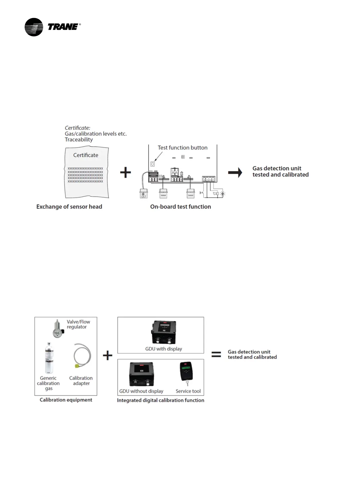
Calibration of this component must be done every year. It is important to ensure proper accuracy and operation of
the detector. There are two different methods to fulll the calibration requirements:
It is necessary to make an order of this sensor head as spare part. After sensor head exchange, the detector must
be tested with the on-board test button function, which simulates alarm signals and relay activation, to ensure all
electrical components are functional.
as new after replacing the sensor head.
Performing a calibration to the sensor using calibration gas (gas mixture with known target gas concentration)
Test equipment and basic competence in Calibration is required to carry out this method. Calibration equipment for
In order to execute the calibration function, the gas detector unit needs to be equipped with a display or connection
to either the service tool or the PC tool.
Calibration has to be carried out every year.
 Loading...


