CLCH-SVX07K-EN 115
Installation - Electrical
.
Note: Air handlers often include optional factory-
provided casing penetration entry points for field-
provided wiring. Consider overall unit
serviceability and accessibility before mounting,
running wires (power), making cabinet
penetrations, or mounting any components to the
cabinet.
The electric heat door may have a solenoid locking
mechanism to prevent opening the control panel while the
electric heater is energized.
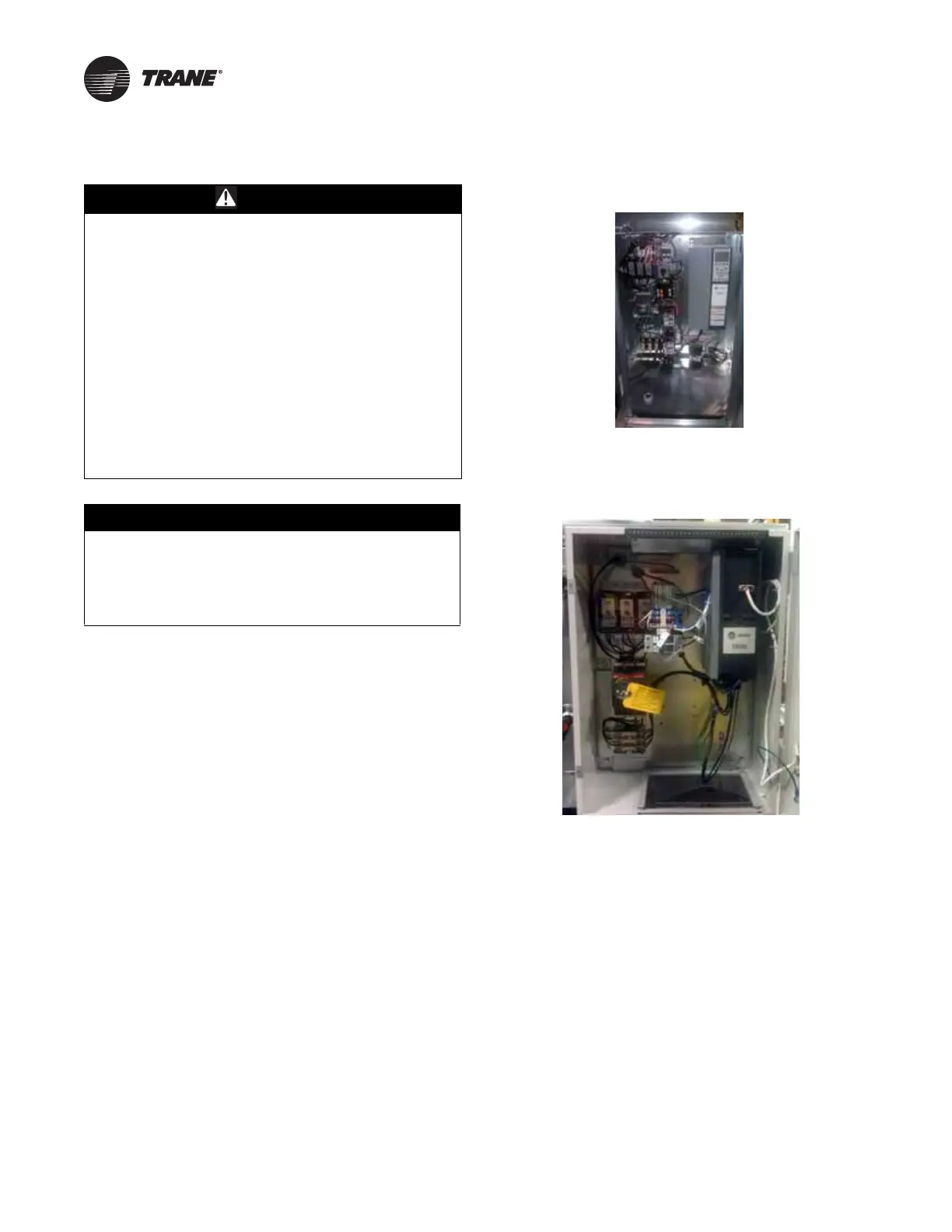
Units intended for indoor use are available with starters or
variable-frequency drives (VFDs) that are externally
mounted in an enclosure or internally mounted in a
recessed cabinet. Units intended for outdoor use are only
available with internally mounted starters or VFDs. A
typical internally mounted VFD is shown in the following
figure.
A typical externally mounted VFD is shown the following
figure.
Motorized impeller control panel (MICP) is mounted in an
external NEMA 4 box and provides a common externally
accessible disconnect switch, power distribution block,
control terminal block and independent motor overcurrent
protection. Motor control connections are brought to the
external enclosure to ease field wiring. This option allows
the fan to be included in a unit single-point power feed and
allows the control signals to be pre-wired into the factor
installed control system. Refer to the following figure for
control panel layout of the three fan configurations.
The control panel’s disconnect handle requires that the
panel be mounted 72 inches or below from the floor. This
limits the option to fan sections on the bottom level on the
unit, or fan sections on the second level for units size 14
and below.
WARNING
Hazardous Voltage w/Capacitors!
Failure to disconnect power and discharge capacitors
before servicing could result in death or serious
injury.Disconnect all electric power, including remote
disconnects and discharge all motor start/run
capacitors before servicing. Follow proper lockout/
tagout procedures to ensure the power cannot be
inadvertently energized. For variable frequency drives
or other energy storing components provided by Trane
or others, refer to the appropriate manufacturer’s
literature for allowable waiting periods for discharge of
capacitors. Verify with an appropriate voltmeter that all
capacitors have discharged.
For additional information regarding the safe discharge
of capacitors, see PROD-SVB06*-EN
NOTICE
Use Copper Conductors Only!
Failure to use copper conductors could result in
equipment damage as the equipment was not
designed or qualified to accept other types of
conductors.
Figure 146. Internally mounted VFD
Figure 147. Externally mounted VFD
 Loading...


