Installation - Mechanical
CLCH-SVX07K-EN 31
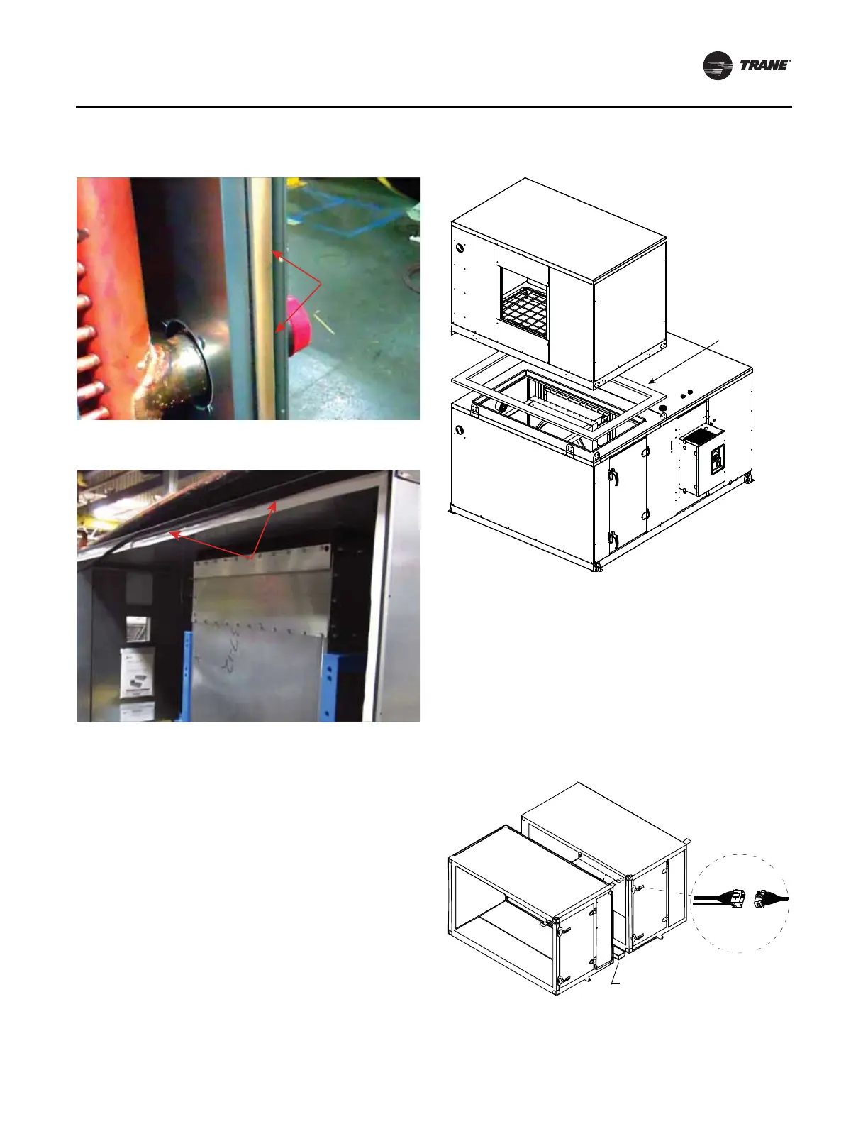
4. If the unit is equipped with factory-mounted controls,
move adjacent subassembly within six inches and
fasten quick connects where the sections bolt together.
See Figure 34 for low voltage. See Figure 35 and
Figure 36 for high voltage.
Note: Reference the appropriate controller manual for
more details on the installation of units with
factory-mounted controls.
Figure 31. Install Butyl tape to outermost edge of panel.
Figure 32. Install gasket to outermost edge of panel
Butyl tape
extends to
outermost
edge of panel
Install gasket to
outermost edge
of panel
Figure 33. Stacked unit assembly (shown for sizes 3-50)
Figure 34. Horizontal section-to-section low voltage
quick connects
Gasket
X23010544010
1.00 inches T
x
4.00 inches W
Use 2 x 4 inch wood to protect
hands from accidental pinching
Low voltage
 Loading...


