Installation - Mechanical
54 CLCH-SVX07K-EN
Stacked Design - Size 3-50
Grade to Roof Mounted (0<=Sds<=1.85) Non-
Isolated
4000 psi concrete. •
• 1/2-inch diameter Hilti Kwik Bolt TZ carbon steel
concrete anchors attached to unit base rails
• Install clips at all ship split corners.
• Install clips at ship splits with a stacked section at 36
inches maximum on-center spacing.
• Install clips at single level ship splits containing fans or
coils at 48 inches maximum on-center spacing.
• 3 1/4-inch minimum anchor embedment
• 7 1/2-inch minimum distance to the nearest edge
• 6-inch minimum concrete slab thickness
Steel dunnage/steel curb.
1/2-inch diameter ASTM A325 or SAE Grade 5 bolts
attached to unit base located as noted above or 1-inch long
3/16-inch welds at unit bases located as noted above.
Ceiling Suspended Units Size 3-30
(0<=Sds<=1.85)
The details for the suspension system, including the steel
members used to support the bottom of the unit, will need
to be determined by working directly with The VMC
Group. They will also help provide information regarding
the required external isolation system.
Anchoring
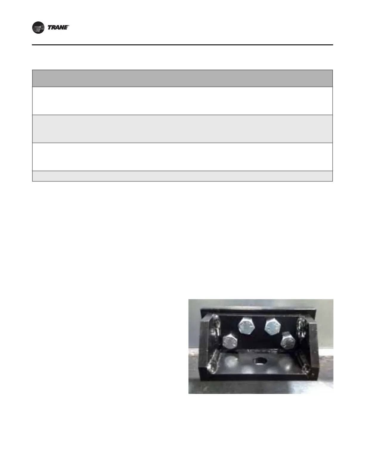
Lifting lugs should be used to anchor the unit at the ends
of each shipping split. Per the anchor requirements,
additional anchoring may be needed. If so, anchors will be
provided and installed on the unit. An example of a seismic
anchor is shown in Figure 71.
Anchor selection meets or exceeds IBC 2000,2003, 2006,
2009, 2012, and CBC 2007, 2010 compliance requirements.
Special Inspection per IBC Section 1704 is required on all
installations. All anchors listed above must be installed to
meet compliance.
Table 11. Anchor requirements
SDS I
p
z/h
Attachment
method
Equipment
weight (lbs.)
Seismic
Restraint
model
Attachment System
Qty per tag Method
1.483 1.5 1.0
Floor mounted
(concrete)
45 psf maximum Bolt down
2 per mounting
location
Anchor: Hilti HDA-P
Dia.: M12 x 125/50
Embed.: 4.922 inches
Edge: 14-in./8-in. thick
Conc.: 3000 psi
0.967 1.5 1.0
Floor mounted
(concrete)
45 psf maximum Bolt down
2 per mounting
location
Anchor: Hilti TZ-CS
Dia.: 1/2 inch
Embed.: 3.25 inches
Edge: 14-in./6-in. thick
Conc.: 3000 psi
1.850 1.5 1.0
Floor mounted
(steel)
45 psf maximum Bolt down
2 per mounting
location
Anchor: A325 Bolt
Dia.: 1/2 inch
Embed.: n/a
Edge: n/a
Conc.: n/a
1.850 1.5 1.0
Floor mounted
(welded to steel)
45 psf maximum Welded
1 per mounting
location
6-inch weld length with
1/8-inch weld leg
Notes: Install clips at shipping split corners.
Install clips at shipping splits containing fans or coils at 48 inches maximum on-center spacing.
Figure 71. Seismic anchor
 Loading...


