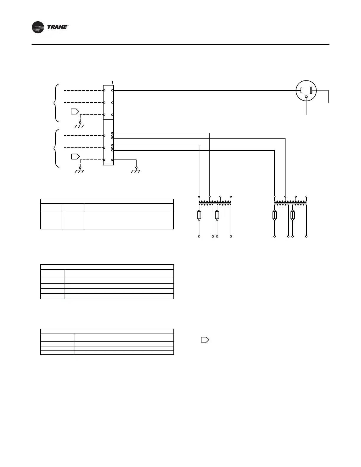
Figure 160. Typical schematic for customer-supplied power for GFCI and lights/switch
Dedicated
GFCI
customer
suppoled
power
(115V)
Custom
supplied
power
(115V)
2TB4
BLK
WHT
GRN
BLK
BLK
WHT
WHT
L5
L6
L1
L2
27
Attach
earth
ground
Attach
earth
ground
1
2
G
H
N
G
27
3GFR1
WHT
BLK
GRN
2T4
115V
BLKWHT
2F75 2F76
24V 24V
X1 X2 X3 X4
To secondary
lighting circuit
To primary
lighting circuit
X1 X2 X3 X4
24V 24V
2F73 2F74
H1 H2 H3 H4 H1 H2 H3 H4
BLKWHT
2T3
115V
Notes:
Dashed lines indicate recommended field wiring by others.
Phantom lines indicate control options.
Ref. Control panel schematic for specific detail.
All field wiring must be in accordance with the National
Electrical Code (NEC), state and local requirements. Other
countries applicable national and/or local requirements
shall apply. Field conductors shall have insulation rating
not less than 600V copper conductors only.
The minimum circuit ampacity, the maximum fuse size, and
disconnect size are calculated based on the inverter input line
currents per Article 430-2 of the National Electrical Code.
Attach ground or equipment ground.
27
1
2
3
Fuse
2F73
to
2F76
Device
Designation
2TP4
2T3
2T4
3GFR1
Lighting Transformer Fuses
P/N
MDL-3-2/10-R (Bussmann)
Voltage
24
Legend
Description
Terminal block GFCI/lighting circuits
Primary lighting transformer
Secondary lighting transformer
Ground fault receptacle
Device Prefix Location Code
Area Location
High voltage panel
Low voltage panel (unit schematic)
Air handler section
1
2
3
 Loading...


