Unit Start Up
128 RT-SVX36K-EN
3. Close the disconnect switch or circuit protector switch
that provides the supply power to the unit's terminal
block 1TB1 or the unit mounted disconnect switch 1S14
to allow the crankcase heater to operate a minimum of
8 hours before continuing.
Note: Compressor Damage could occur if the crankcase
heater is not allowed to operate the minimum of 8
hours before starting the compressor(s).
4. Turn the 115 volt control circuit switch 1S1 and the 24
volt control circuit switch 1S70 to the “On” position.
5. Open the Human Interface access door, located in the
unit control panel, and press the SERVICE MODE key to
display the first service screen. Refer to the latest
edition of the RT-SVP01*-EN for CV applications or RT-
SVP02*-EN for VAV applications for the SERVICETEST
screens and programming instructions.
6. Use Table 42, p. 96 to program the following system
components for operation by scrolling through the
displays;
• 20to36Ton
– Compressor 1A (On)
– Compressor 1B (Off)
– Condenser Fans
• 40 through 75Ton (VSC units only)
– Compressor 1A (On)
– Compressor 2A (Off)
– Compressor 2B (Off)
– Condenser Fans
• 40 through 130Ton
– Compressor 1A (On)
– Compressor 1B (Off)
– Compressor 2A (Off)
– Compressor 2B (Off)
– Condenser Fans
7. Attach a set of service gauges onto the suction and
discharge gauge ports for each circuit. Refer to
Figure 84, p. 130 for the various compressor locations.
8. Once the configuration for the components is
complete, press the NEXT key until the LCD displays
the “Start test in __Sec.” screen. Press the + key to
designate the delay before the test is to start.This
service test will begin after theTEST START key is
pressed and the delay designated in this step has
elapsed. Press the ENTER key to confirm this choice.
9. Press theTEST START key to start the test. Remember
that the delay designated in step 8 must elapse before
the system will begin to operate.
10. It is very important to review and follow the Electrical
Phasing procedure described in the startup procedure
of the IOM. If the compressors are allowed to run
backward for even a very short period of time, internal
compressor damage may occur and compressor life
may be reduced. If a scroll compressor is rotating
backwards, it will not pump, make a loud rattling sound
and low side shell gets hot. Immediately shut off the
unit. If the phasing is incorrect, interchange any two
compressor leads to correct the motor phasing.
11. Press the STOP k ey at the Human Interface Module in
the unit control panel to stop the compressor
operation.
12. Repeat steps 5 through 11 for each compressor stage
and the appropriate condenser fans.
Refrigerant Charging
1. Attach a set of service gauges onto the suction and
discharge gauge ports for each circuit. Refer to
Figure 84, p. 130 for the various compressor locations.
2. Open the Human Interface access door, located in the
unit control panel, and press the SERVICE MODE key to
display the first service screen. Refer to the latest
edition of the programming manual for CV or VAV
NOTICE:
Compressors Damage!
Do not allow liquid refrigerant to enter the suction line.
Excessive liquid accumulation in the liquid lines could
result in compressor damage.
COMPRESSOR SERVICE VALVES MUST BE FULLY
OPENED BEFORE START-UP (SUCTION, DISCHARGE,
AND LIQUID LINE)
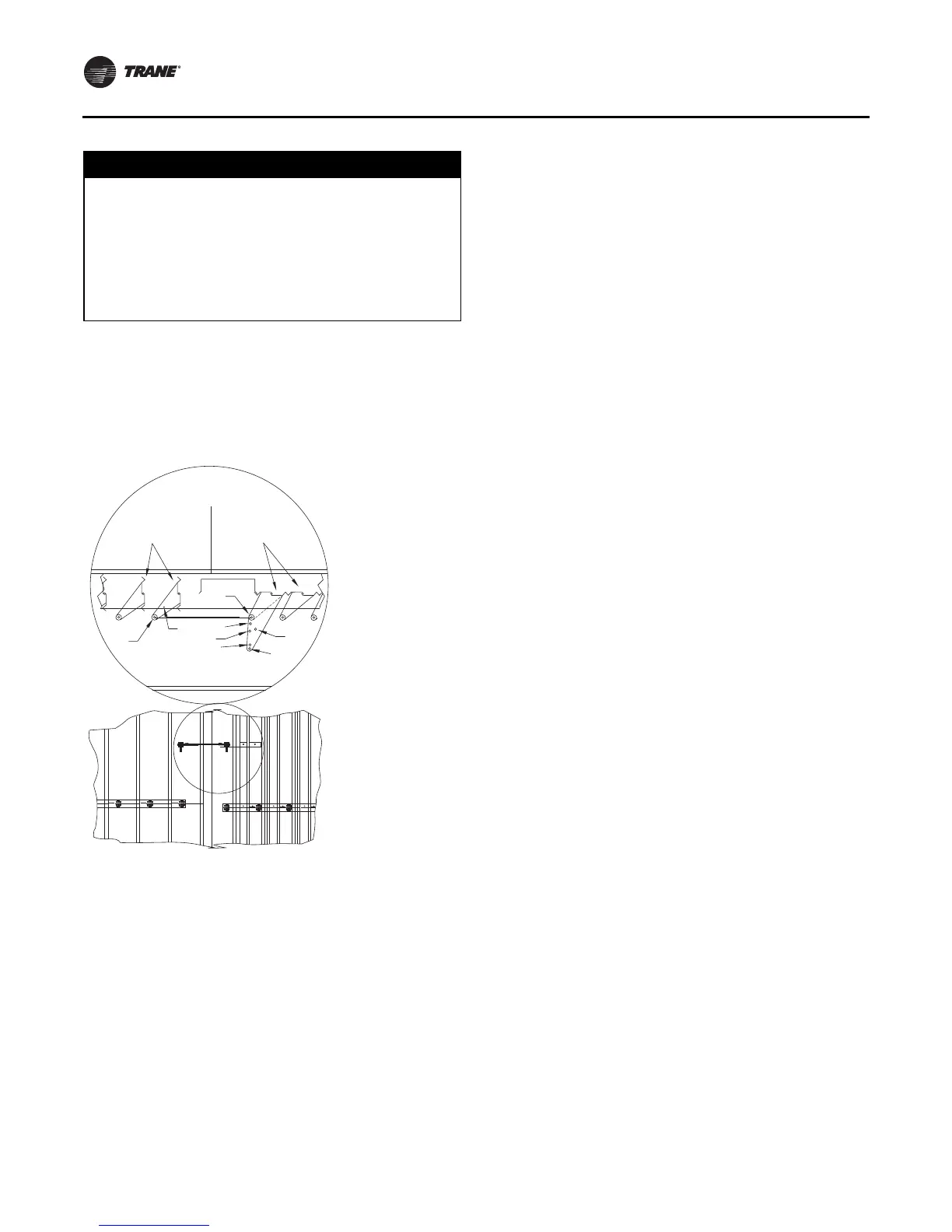
Figure 83. Outside air and return air linkage adjustment
RETURN AIR
DAMPERS
OUTSIDE AIR
DAMPERS
FILTER
SECTION
2
1
3
4
5
6
7
8
Top View

 Loading...


