Installation
42 RT-SVX36K-EN
Units with Gas Furnace
Units equipped with a gas furnace have a 3/4” CPVC drain
connection stubbed out through the vertical support in the
gas heat section. It is extremely important that the
condensate be piped to a proper drain. Refer to the
appropriate illustration in Figure 14 and Figure 15 for the
location of the drain connection.
Note: Units equipped with an optional modulating gas
furnace will likely operate in a condensing mode
part of the time.
An additional 1-1/4” non-connectable water drain is
located in the base rail within the heating section.
Ensure that all condensate drain line installations comply
with applicable building and waste disposal codes.
Removing Supply and Exhaust/Return Fan
Shipping Channels (Motors >5Hp)
Each FC supply fan assembly and exhaust fan assembly
for S_HL units shipped with a motor larger than 5 HP is
equipped with rubber isolators (as standard) or optional
spring isolators. Each DDP supply fan assembly for SAHF
and SXHL units is equipped with spring isolators. Each
return fan assembly for S_HL units shipped with a motor
larger than 5 HP is equipped with spring isolators.
Shipping channels are installed beneath each fan
assembly and must be removed.To locate and remove
these channels, refer to Figure 26 and Figure 28, and use
the following procedures:
Rubber Isolators:
1. Remove and discard the shipping bolts from the fan
assembly rails.
2. Elevate the fan-and-motor assembly and slide the
shipping channels out from between the fan assembly
rails and the unit's base rail.
3. Lower the fan-and-motor assembly onto the isolators.
Make sure that the pins at the top of the isolators are
engaged in the corresponding holes on the fan
assembly.
4. Verify that the fan assembly is being supported by the
isolators.
Spring Isolators: See Figure 26, Figure 28, Figure 27
and Figure 29 for spring isolator locations.
1. Remove and discard the shipping tie down bolts.
2. Remove the shipping channels and discard.
Note: Fan assemblies not equipped with rubber or spring
isolators have mounting bolts at the same
locations and must not be removed.
Note: If return fan backside spring isolator repair/
replacement is required, access the backside of the
return fan by entering the unit filter section.
Remove the top pivot bearings from the three
fixed- position return damper blades (bolted
together as a single section with an angle brace).
Lift the three-blade section as a single unit from the
return damper assembly and set aside or lean in
against the return fan frame.Then enter the return
fan compartment from the filter section to perform
service work on the rear isolators.
Optional DDP Supply Fan Shipping
Channel Removal and Isolator Spring
Adjustment
ShippingTie Down and Isolator Spring Adjustment-
Remove shipping tie down bolt and washer (4 - 20 to 30
ton,6-40to55ton,8-60to75ton). Leave shipping
channels in place. Verify spring height is 0.1" to 0.2"
above shipping channel. Spring height is factory set but
verify and adjust as needed by: 1) Back off ALL spring
isolator jam nuts (4) at top of assembly (adjusting one
spring effects all others) 2) Turn adjustment bolt (make
small adjustments, again each change effects all other
springs. Clockwise raises, Counter clockwise lowers).
When correctly adjusted re-tighten jam nuts and remove
shipping channels. Do Not Remove electrical
ground wire strap between isolation base and unit
base.
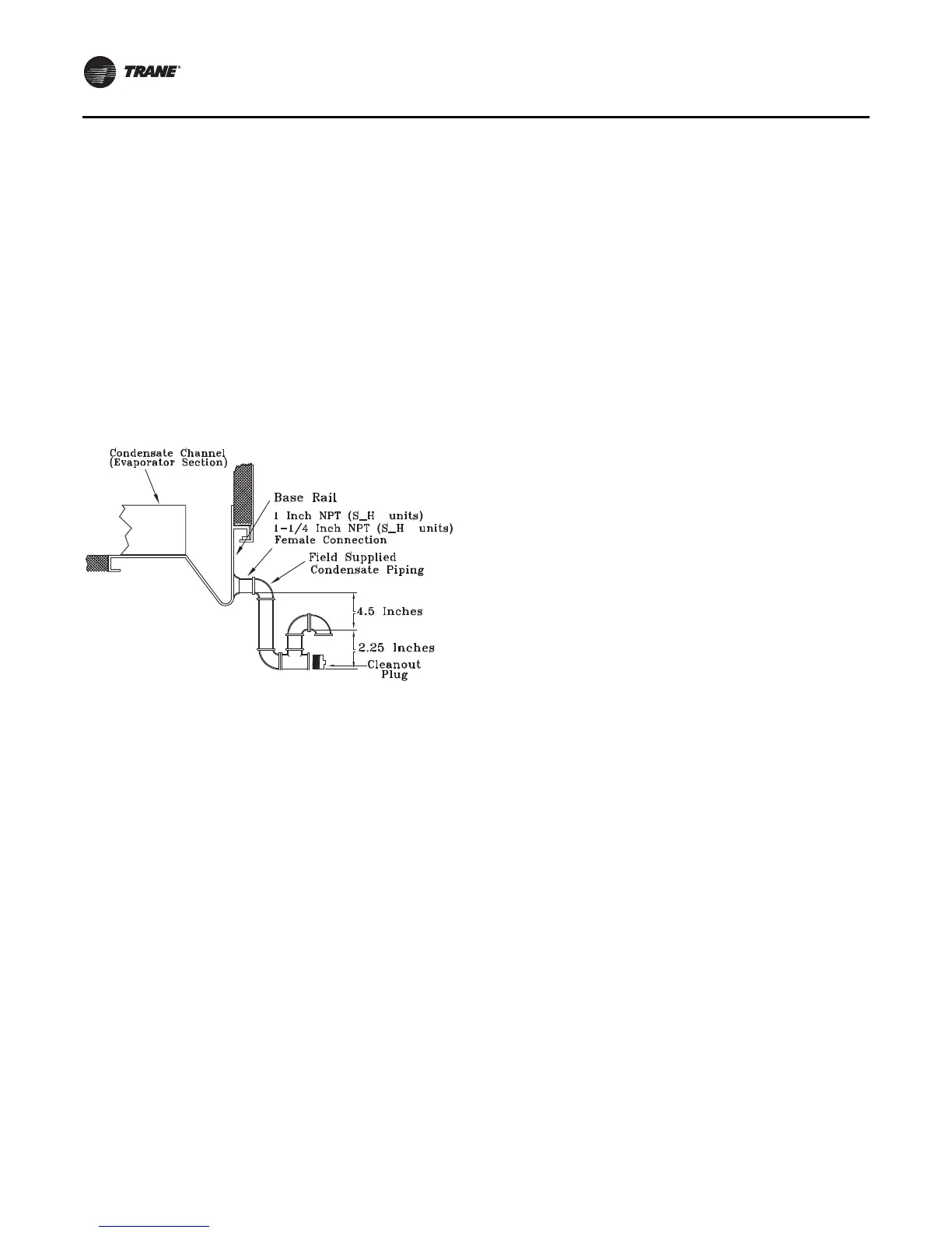
Figure 24. Condensate trap installation
L
G

 Loading...


