General Information
RT-SVX36K-EN 21
100%. On units with a VSPD Compressor, during
Unoccupied Cooling operation theVSPD Compressor will
be controlled at its 100% capacity as applied to the unit.
TheVSPD Compressor will be staged On/Off as a standard
staged compressor.
Supply Air Tempering
On DischargeTemperature Control units equipped with
“Modulating Heat”, if the supply air temperature falls 10°F
below the supply air temperature setpoint, the hydronic or
modulating gas heat valve will modulate to maintain the
supply air temperature to within the low end of the
setpoint deadband.
Supply Duct Static Pressure Control
(Occupied)
The RTM relies on input from the duct pressure transducer
when a unit is equipped with a Variable Frequency Drive.
The unit controls will raise or lower the supply fan speed
to maintain the supply duct static pressure to within the
static pressure setpoint deadband. Figure 6 below shows
the pressure transducer output voltage relationship to
input pressure.The unit is comparing supply duct
pressure to ambient (outside) pressure.The pressure
transducer input is factory piped to measure the pressure
in the discharge section of the unit. Refer to Figure 29 to
see how the transducer tubing is connected.
Supply Duct Static Pressure Control
(Occupied)
The RTM relies on input from the duct pressure transducer
when a VAV unit is equipped with a Variable Frequency
Drive.This input allows the unit to control the supply fan
speed in order to maintain the supply duct static pressure
to within the static pressure setpoint deadband.
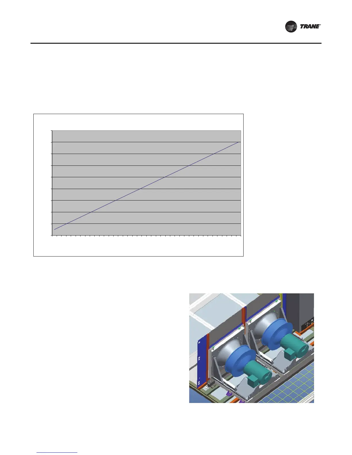
Direct Drive Plenum (DDP) Supply Fan Option
DDP supply fans are positioned down stream of the fan
board. DDP option includes a grate welded in the unit
discharge opening. 20-55 ton sizes are single fan, 60-75 ton
sizes (shown) have two fan assemblies.
Figure 6. Transducer voltage output vs. pressure input (supply, return, space pressure)
-0.75 to 9.0 Iwc Pressure Transducer Voltage Output vs. Pressure Input
0.00
0.50
1.00
1.50
2.00
2.50
3.00
3.50
4.00
4.50
-0.
75
-0.
25
0.
2
5
0.
7
5
1.
2
5
1.
7
5
2.
2
5
2.
7
5
3.
2
5
3.
7
5
4.
2
5
4.
7
5
5.
2
5
5.
7
5
6.
2
5
6.
7
5
7.
2
5
7.
7
5
8.
2
5
8.
7
5
Pressure (inches w.c.)
Volts
Figure 7. DDP supply fan