Maintenance
182 RT-SVX36K-EN
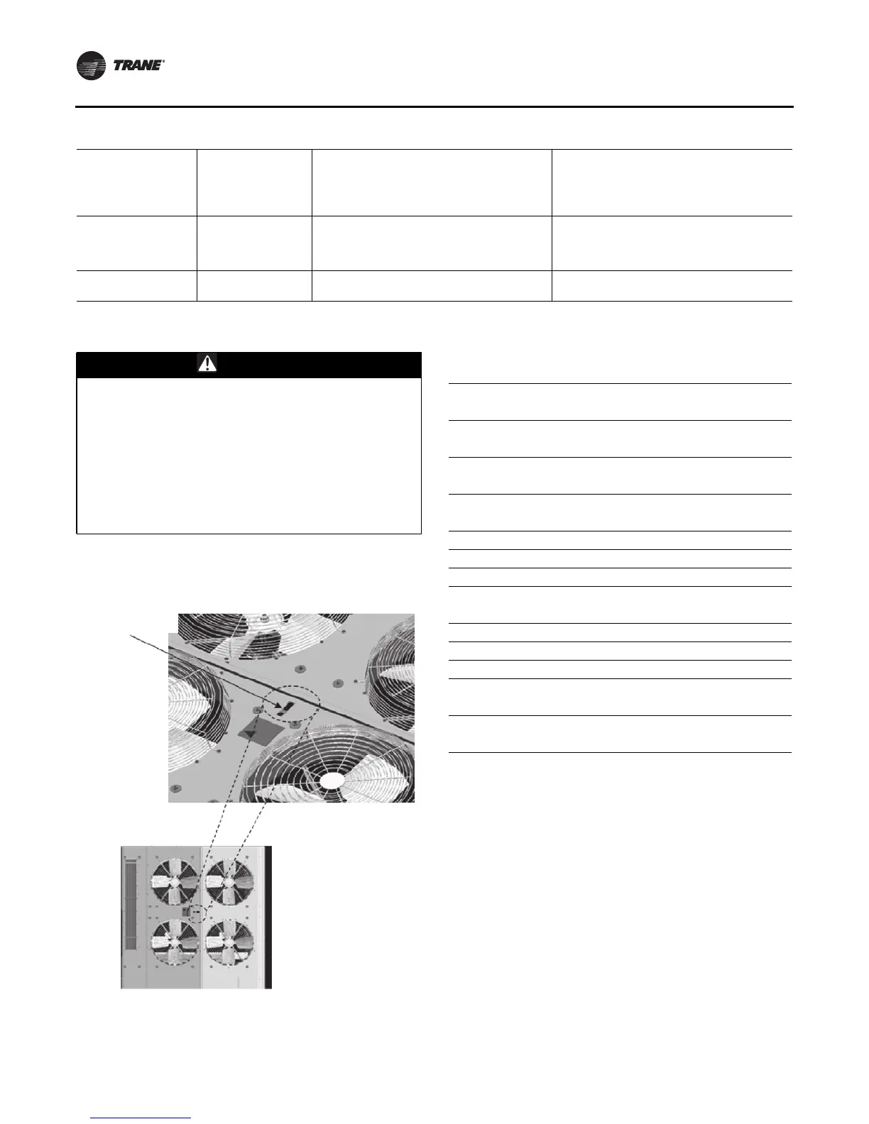
Fall Restraint
The fall restraint is located approximately 3 feet from the
unit edge. Figure 137, p. 182
Final Process
For future reference, you may find it helpful to record the
unit data in the blanks provided.
Sump Pump Does not run
Sump Pump Overload Trip Low Water Level or
faulty float switch. Unit in ‘Dry Mode’ Operation
Reset – check amps on each leg to determine if
faulty motor. Check and clean debris around float
switch. Check Ambient thermostat setting and
mode of operation (close on rise). See section 2
for T’stat setup instructions.
Sump Pump Low Flow
Pump may be operating backwards or impeller
inlet may be slightly blocked.
Change pumping direction by changing any two
legs to the pump motor. Disconnect Power and
remove pump to inspect for possible impeller
obstruction.
Spray Nozzle Dry area on coil
Check for proper spray pattern over each
quadrant.
Remove debris from clogged nozzle.
Table 79. Evaporative Condenser Models—Maintenance and Troubleshooting (continued)
WARNING
Falling Off Equipment!
This unit is built with fall restraint slots located on unit
top that MUST be used during servicing. These slots
are to be used with fall restraint equipment that will
not allow an individual to reach the unit edge. However
such equipment will NOT prevent falling to the ground,
for they are NOT designed to withstand the force of a
falling individual. Failure to use fall restraint slots and
equipment could result in individual falling off the unit
which could result in death or serious injury.
Figure 137. Fall restraint
Fall restraint
Complete Model Number:
Unit Serial Number:
Unit “DL” Number (“Design special” units only):
Wiring diagram numbers (from unit control panel):
-schematic(s)
-connections
Unit Address (TCI)
Network ID (LCI or BCI)

 Loading...


