Installation
RT-SVX36K-EN 41
Requirements for Steam Heat (SSH_)
• Install an automatic air vent at the top of the return
water coil header.
• Route properly sized steam piping through the base of
the unit into the heating section.
• Install the factory-supplied, 2-way modulating valve
• Complete the valve actuator wiring.
• Install 1/2”, 15-degree swing-check vacuum breaker(s)
at the top of each coil section. Vent breaker(s) to the
atmosphere or merge with return main at discharge
side of steam trap.
• Position the steam trap discharge at least 12" below the
outlet connection on the coil.
• Use float and thermostatic traps in the system, as
required by the application.
O/A Pressure Sensor and Tubing
Installation (All units with Statitrac or
Return Fans)
• O/A pressure sensor mounted to the roof bracket.
• Factory supplied pneumatic tubing installed between
the O/A pressure sensor and the connector on the
vertical support.
• Field supplied pneumatic tubing connected to the
proper fitting on the space pressure transducer located
in the filter section, and the other end routed to a
suitable sensing location within the controlled space
(Statitrac only).
Requirements for Modulating Reheat
Dehumidification (S_HL)
• Install (5U108) humidity sensor in space or return duct
• Complete field wiring of humidity sensor to ECEM
(1TB16). Refer to “Field Installed Control wiring” for
guidelines.
Condensate Drain Connections
Each S_HL and S_HK unit is provided with 1" evaporator
condensate drain connections (two on each side of the unit
for FC supply fans and one on each side of the unit for DDP
supply fans).
Due to the size of these units, all condensate drain
connections must be connected to the evaporator drain
connections. Refer to the appropriate illustration in
Figure 14 and Figure 15 for the location of these drain
connections.
Condensate traps must be installed because drain
connections are in a negative pressure environment.
Install the P-Traps at the unit using the guidelines in
Figure 24.
Pitch the drain lines at least 1/2 inch for every 10 feet of
horizontal run to assure proper condensate flow. Do not
allow the horizontal run to sag causing a possible double-
trap condition which could result in condensate backup
due to “air lock”.
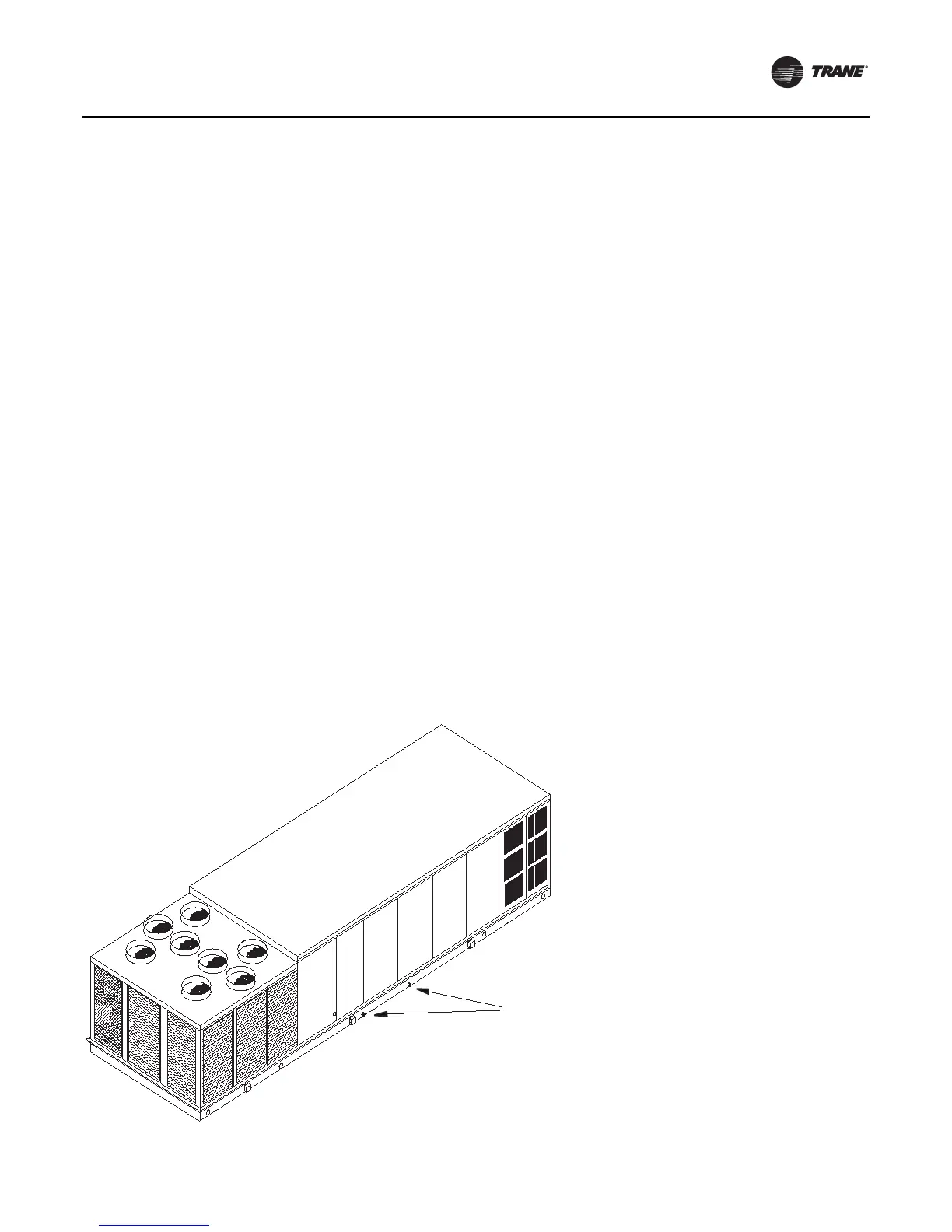
Figure 23. Condensate drain locations
Condensate drain openings
both sides
Note: Each drain pan connection must be trapped.
The drains may be trapped individually or
connected and then trapped.

 Loading...


