34
L8V1-SVX001-1A-EN
Return Air Filters
TYPICAL AIR FILTER INSTALLATIONS
Filters are not factory supplied for furnaces. Filter size needed will be
dependent on type of filter and CFM requirement. Filters must be
installed externally to the unit.
Important: It is recommended to transition return ducting to the
same size as the opening. It is acceptable for return duct
or filter frame to extend forward of the opening but
plastic plugs MUST be installed in any opening that the
duct or filter frame may cover.
Return Air Filters
Furnace Width Bottom Return Filter
Qty and Size
14.5" 1 — 14” x 25” x 1”
17.5" 1 — 16” x 25” x 1”
21.0” 1 — 20” x 25” x 1”
Note: For upflow airflow furnaces where the airflow requirement
exceeds 1600 CFM - Furnaces will require return air openings
and filters on: (1) both sides, or (2) one side and the bottom,
or (3) just on the bottom.
Preparation for Upflow Bottom and Side Return Air Filter
Installations
All return air duct systems should provide for installation of return air
filters.
1. Determine the appropriate position to set the furnace in order to
connect to existing supply and return ductwork.
2. For upflow side return installations, remove the insulation around
the opening in the blower compartment
3. The side panels of the upflow furnace include locating notches
that are used as guides for cutting an opening for return air, refer
to the figure and the upflow furnace outline drawing for duct
connection dimensions for various furnaces.
4. If a 3/4" flange is to be used for attaching the air inlet duct, add to
cut where indicated by dotted lines. Cut corners diagonally and
bend outward to form flange.
5. If flanges are not required, and a filter frame is installed, cut
between locating notches as in illustration.
6. The bottom panel of the upflow furnace must be removed for
bottom return air.
*
*
*
*
UPFLOW FURNACES ONLY
LOCATING
NOTCHES
PROVIDED
FOR SIDE
RETURN
CUTOUT
* SEE OUTLINE DRAWING
FRONT OF
FURNACE
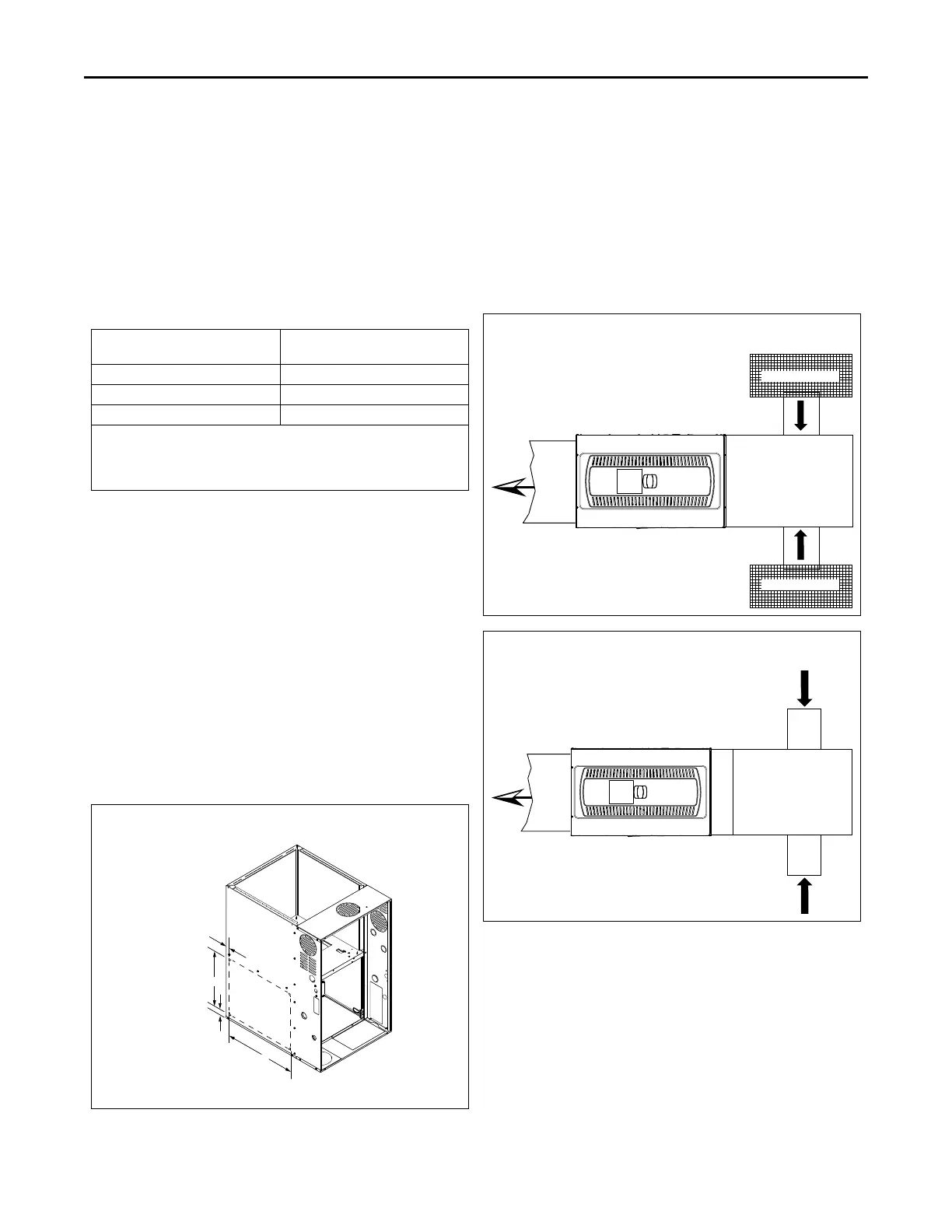
RETURN AIR FILTERS FOR MODULAR BLOWER IN
HORIZONTAL CONFIGURATION
When the modular blower is installed in the horizontal configuration,
the return air filters must be installed exterior to the modular blower
cabinet. Remote filter grilles may be used for homeowner
convenience, refer to Figure 3, p. 34 or the filters may be installed in
the duct work upstream of the modular blower, refer to
Figure 4, p. 34.
Filter kits are available for horizontal applications.
Direct coupled side returns are not allowed to the blower
cabinet.
Figure 3. Remote Filter Installation
Remote Filter Grille
Remote Filter Grille
Figure 4. Duct Filter Installation
FFuurrnnaaccee GGeenneerraall IInnssttaallllaattiioonn
 Loading...