BAS-SVX33F-EN 13
Installing the Power Supply Module
Power and Field Wiring
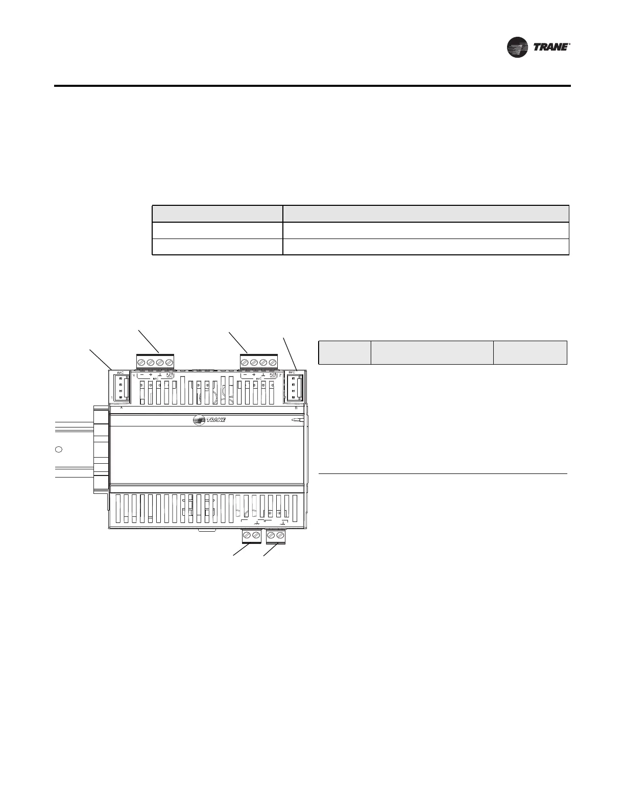
After the power supply module has been properly mounted, install input power and field wiring.
Use 18 AWG wire as recommended in Table 4. Refer to Figure 5 for wiring connection locations on
the power supply module. Refer to Table 5 for the recommended connectors.
Note: The maximum wire length for 18 AWG wire is 50 feet (15 m). Longer lengths result in
excessive voltage drop and would then require 16 AWG wire.
Installing Power Input Wire
Follow these steps to install power input wiring:
1. Perform lockout/tagout procedures for line voltage power to the cabinet.
2. Install power input wire for the 24 Vac input connection by using 18 AWG wire and the
recommended connector (
Table 5).
Note: Strip the wire to expose 0.28 in. (7mm) of bare wire for inserting into the terminal blocks.
After tightening the screws, verify that the wire cannot be easily pulled out by lightly tugging
on each wire. For reference, the screw terminals should be tightened to 0.5 to 0.6 N-m (71-
85 Ozf-in, 4.4-5.3 Lbf-in)
Table 4. Recommended wire sizes
Purpose Wire Size
Power input terminals 18 AWG
Field-wiring connections 18 AWG
Figure 5. Wiring connections
PM014
24
VAC
XFMR
OUT
24
VAC
Table 5. Recommended connectors
(a) The + and - terminals are for the IMC bus comm lines. The power
supply module transmits IMC communication signals and can provide
power to connected modules. Module s can be wired into one of the
connectors to obtain access to power and communications for the en-
tire IMC link.
(b) The 24 Vac input connection must be connected to functional earth
ground for referencing the IMC bus and for electromagnetic compat-
ibility.
Location Description
Recommended
Connector
1
IMC pin connection
CAB01202 or
CAB01203
2
IMC plug-type terminal block
(a)
CON00431
3
IMC plug-type terminal block
(a)
CON00431
4
IMC pin connection
CAB01202 or
CAB01203
5
24 Vac output CON00429
6
(b)
24 Vac input CON00429
1
6
3
5
2
4
 Loading...