40 RTAA-SVX01A-EN
Installation — Remote Evaporator
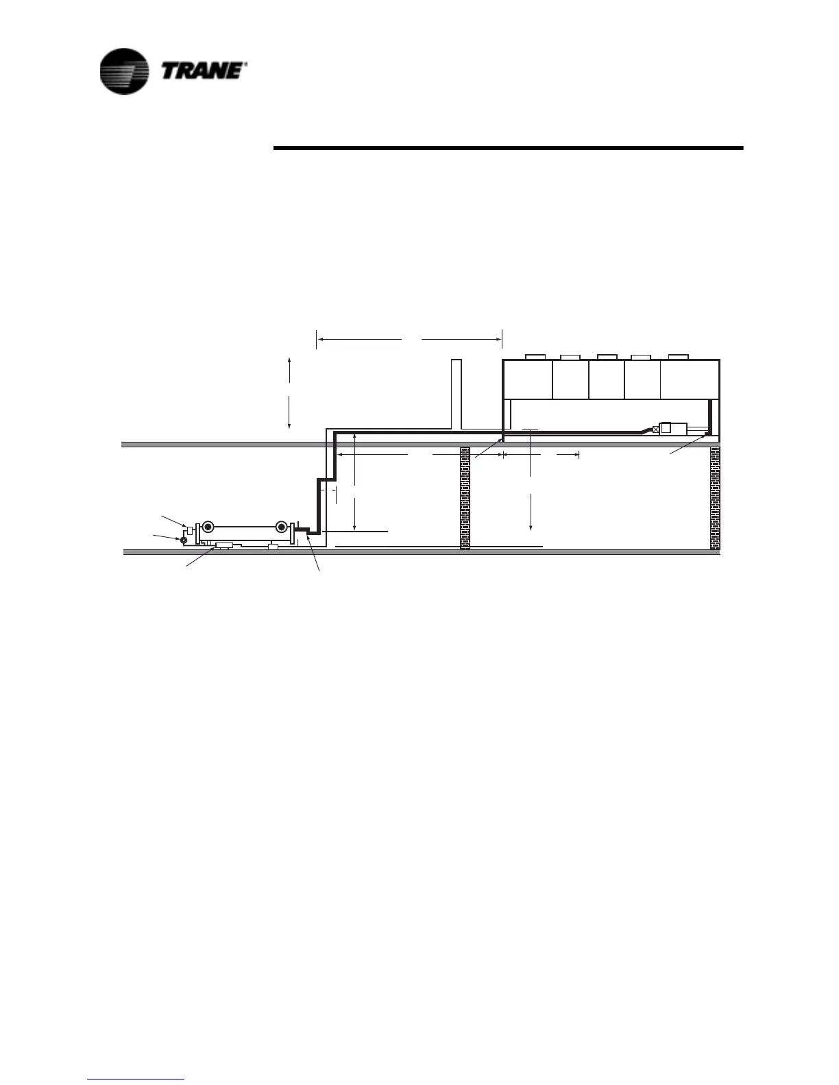
9. From Table 4, for a 50 ton circuit, for 125 equivalent feet (also nearest to
128.2 feet), the OD is still:
Horizontal or Downflow = 1 1/8 inches
10. From 22, there is 8 feet of up-flow on the liquid line inverted trap. There-
fore, select:
Upflow = 1-3/8 inches
Suction Line Sizing Steps
The steps to compute suction line size are as follows:
1. Break the suction line into it's “Upflow” and “Horizontal or Downflow”
components. The horizontal or downflow length should include that
portion of field-installed suction line within the condensing unit's base.
See Figure 22.
2. From Tabl e 5, select the appropriate “Upflow” suction line outside diame-
ter according to the circuit tonnage. This is the diameter of the upflow
suction line and any fittings in the upflow line.
3. With the diameter found in step #2, use Table 3 to find the equivalent
length of each fitting in the upflow line. Sum the equivalent lengths of all
the fittings in the upflow line.
4. Sum the final length found in step #3 with the actual length of the upflow
line. This is the final equivalent length of the upflow portion of the suction
line.
5. Multiply by 1.5, the actual length of the horizontal or downflow portion of
the suction line.
6. Add the length from step #5 to the length from step # 4. This is the first
estimate of the equivalent line length.
7. In Table 6 find the column for the circuit tonnage you are sizing. In that
Figure 22 Liquid Line Sizing Example
&RQGHQVHU&RLO
/LTXLG/LQH
6XFWLRQ
$FFXPXODWRU/LQH
&RPSUHVVRU
5HPRWH(YDSRUDWRU
(;9
6LJKW
*ODVV
)LOWHU
'ULHU
/LTXLG7UDS
87XEH
µ
6XFWLRQ/LQH7UDS
 Loading...


