68 RTAA-SVX01A-EN
Operating Principles
Compressor Rotors
The compressor is a semi-hermetic, direct-drive helical rotary type
compressor. Each compressor has two rotors - “male” and “female” - which
provide compression. See Figure 33 The male rotor is attached to, and driven
by, the motor, and the female rotor is, in turn, driven by the male rotor.
Separately housed bearing sets are provided at each end of both rotors.
The helical rotary compressor is a positive displacement device. The refrig-
erant from the evaporator is drawn into the suction opening at the end of the
motor barrel, through a suction strainer screen, across the motor, and into the
intake of the compressor rotor section. The gas is then compressed and
discharged directly into the discharge line.
There is no physical contact between the rotors and compressor housing.
The rotors contact each other at the point where the driving action between
the male and female rotors occurs. Oil is injected along the top of the
compressor rotor section, coating both rotors and the compressor housing
interior. Although this oil does provide rotor lubrication, its primary purpose is
to seal the clearance spaces between the rotors and compressor housing.
A positive seal between these internal parts enhances compressor efficiency
by limiting leakage between the high pressure and low pressure cavities.
Capacity control is accomplished by means of two unloader valve assemblies
in the rotor section of the compressor. The female rotor valve is a two-
position valve and the male valve is an infinitely variable position valve. See
Figure 33.
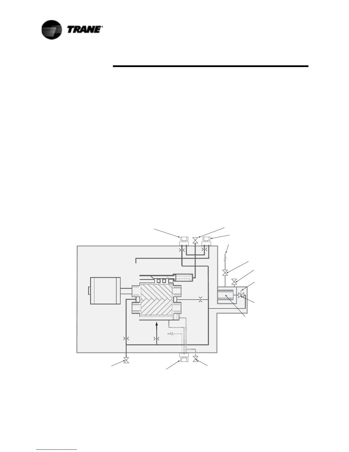
Figure 33 RTAA Refrigerant and Oil Diagram
6FKUDGHU
9DOYH
6FKUDGHU
9DOYH
6FKUDGHU9DOYH
6FKUDGHU
9DOYH
)HPDOH
8QORDGHU
6ROHQRLG9DOYH
0DVWHU
2LO9DOYH
'LVFKDUJH
3UHVVXUH
,QWHJUDWHG
2LO)LOWHU
4XLFN&RQQHFW6KXWRII
9DOYHRU$QJOH9DOYH
)URP2LO&RROHU
0DOH8QORDG
6ROHQRLG9DOYH
0DOH/RDG
6ROHQRLG
9DOYH
0DOH
)HPDOH
0RWRU
6XFWLRQ
6XFWLRQ
6XFWLRQ
7R5RWRU
2LO,QVSHFWLRQ
'LVFKDUJH
3UHVVXUH
 Loading...


