RTAA-SVX01A-EN 67
Operating Principles
Compressor Description
The compressors used by the Model RTAA Series “R” Air-cooled chiller
consists of two distinct components: the motor and the rotors.
Compressor Motor
A two-pole, hermetic, squirrel-cage induction motor (3600 rpm) directly drives
the compressor rotors. The motor is cooled by suction refrigerant gas from
the evaporator, entering the end of the motor housing through the suction
line.
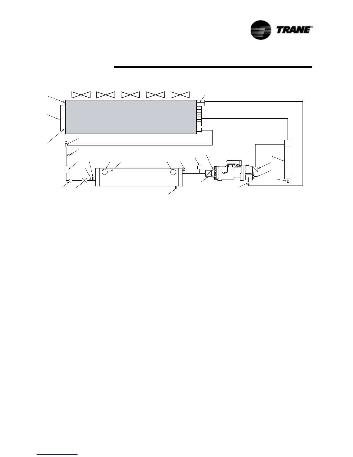
Figure 32 RTAA Refrigeration System and Control Components
&RQGHQVHU
(YDSRUDWRU
1. Discharge Service Valve 9. Subcooler 17. Saturated Evaporator Rfgt.
Temp. Sensor
2. Oil Separator 10. Low Pressure Switch 18. Relief Valve
3. 1/4" Angle Valve 11. Liquid Line Service Valve
(Backseat Port Upstream)
19. Compressor Suction Rfgt. Temp
Sensor
4. Oil Cooler 12. Schrader Valve 20. Suction Service Valve
5. Quick Connect Shutoff
Valve or Angle Valve
13. Filter/Dryer 21. Evaporator Entering Water
Temp. Sensor
6. Oil Temperature Sensor 14. Sight Glass 22. Evaporator Leaving Water
Temp. Sensor
7. Condenser 15. Electronic Expansion Valve 23. Entering Water Connection
8. Saturated Condenser Rfgt.
Temp Sensor
16. 1/4" Angle Valve 24. Leaving Water Connection
 Loading...


