RLC-SVX19G-GB
168
4 UNT-PRC002-GB
Technical Data
FWD 08 12 20 30 45
Power supply (V/Ph/Hz) 230/1/50
Capacities
Cooling capacity on water (1) (kW) 5,2 8,3 15 18,8 30,1
Heating capacity on water (2) (kW) 6,3 11,9 18,9 20,9 38,2
Fan motor (type) 2 x direct drive centrifugal
Fan power input (3) (kW) 0,23 0,46 0,65 1,04 1,51
Current amps (3) (A) 1,1 2,2 3,1 4,7 5,5
Start-up amps (A) 3,2 5,5 9,3 14,1 16,5
Air flow
minimum (m
3
/h) 490 980 1400 1800 2700
nominal (m
3
/h) 820 1650 2300 3000 4500
maximum (m
3
/h) 980 1970 2600 3600 5400
Main coil
Water entering/leaving connections (type) ISO R7 rotating female
(Dia) 3/4" 3/4" 1 1/2" 1 1/2" 1 1/2"
Electric heater (accessory for blower only)
Electric power supply (V/Ph/Hz) 230/1/50 230/1/50 or 400/3/50 400/3/50 400/3/50 400/3/50
Heating capacity (kW) 2/4 8 10 12 12
Hot water coil (accessory for blower only)
Heating capacity (4) (kW) 6,3 12 17,4 22,4 34,5
G2 filter (filter box accessory)
Quantity 2 2 2 2 2
Dimensions ( LxWxth) (mm) 386x221x8 486x271x8 586x321x8 586*421*8 586*621*8
G4 filter (filter box accessory)
Quantity - 2 2 2 2
Dimensions ( LxWxth) (mm) - 486x264x48 586x314x48 586*414*48 586*614*48
Condensate pump (accessory) (type) Centrifugal
Water flow - lift height (l/h - mm) 24 - 500
Not available for FWD30 and FWD45
Sound level (L/M/H speed)
Sound pressure level (5) (dB(A)) 36/40/43 38/41/44 46/50/53 47/52/57 47/52/58
Sound power level (5) (dB(A)) 46/50/53 48/51/54 56/60/63 57/62/67 57/62/68
Unit dimensions
Width x Depth (mm) 890 x 600 1090 x 710 1290 x 820 1290 x 970 1290 x 1090
Height (mm) 250 300 350 450 650
Shipped unit dimensions
Width x Depth (mm) 933 x 644 1133 x 754 1333 x 864 1333 x 1008 1333*1133
Height (mm) 260 310 360 460 660
Weight (kg) 32 46 61 76 118
Colour galvanised steel
Recommended fuse size
Unit alone (aM/gI) (A) 8/16 8/16 8/16 8/25 8/25
Unit with electric heater (gI) (A) 16 (2kW),25 (4kW) 40 (230V),3*16 (400V) 3*20 3*25 3*25
(1) Conditions: Water entering/leaving temperature: 7/12 °C, Air inlet temperature 27/19°C DB/WB - Nominal air flow
(2) Conditions: Water entering/leaving temperature: 50/45 °C, Air inlet temperature 20°C DB - Nominal air flow
(3) At high speed with nominal air flow.
(4) Water entering/leaving temperature 90/70 °C, air inlet temperature 20 °C DB, Nominal air flow.
(5) A rectangular glass wool duct 1m50 long is placed on the blower.The measurement is taken in the room containing the blower unit.
Heat exchanger operating limits:
FWD:
*water temperature: max 100° C
*absolute service pressure: min 1 bar/max 11 bars
Accessories - Hot water coil:
*water temperature: min. +2° C/max. 100° C
*absolute service pressure: min 1 bar/max 11 bars
Periodic Maintenance
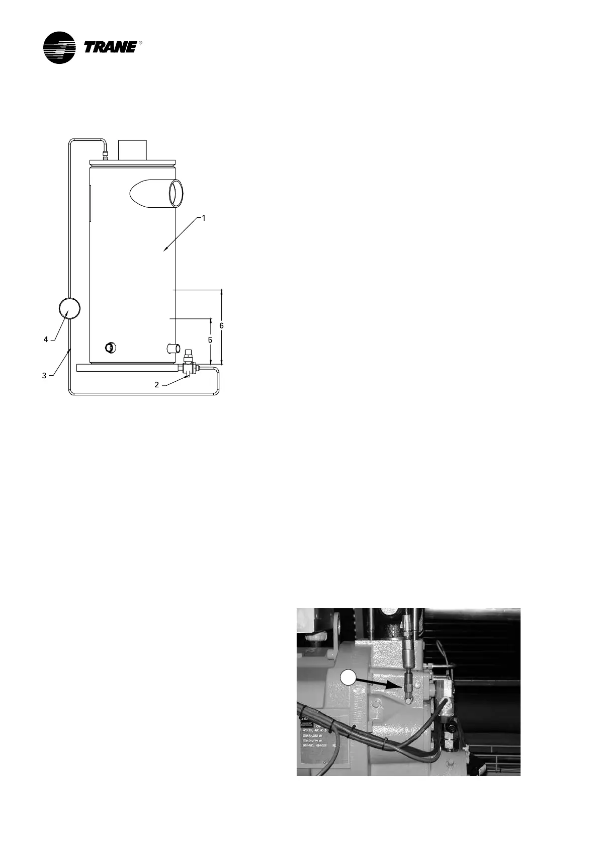
Figure 37 – Oil system schematic: Oil level measurement.
1 = Oil separator
2 = Valve
3 = 1/4” refrigeration hose
4 = Sight glass
5 = Minimum oil level
6 = Maximum oil level
How to measure the oil level:
1. Use the oil drain valve on the oil line and the
service valve on the oil separator (bottom side). This
measurement can be made, when the circuit is not
running. Note: the bottom plate of the oil separator is
approximately 25mm thick.
2. The initial oil charge should be approximately at the
level in of the above chart. This is the approximate
oil level if all the oil is in the oil lines, filter, and oil
sump, and the unit is in vacuum so that there is no
refrigerant dissolved in the oil.
3. After the unit has run for a while, the oil level in the
sump can vary greatly. However, if the unit has run at
“normal” conditions for a long time, the level should
resemble the level in the above chart: Minimum level
should be 50 mm, maximum should be 115 on 8” oil
separators (compressors type M or L), 140 mm on
10” oil separators (compressor typ N) and 147 mm
on 12” oil separators. However excessive oil in the
system will deteriorate the evaporator approach
temperature.
The field charging procedure depends on the
circumstances that resulted in the need for oil charge.
1. Some services procedures may result in loss of
small quantities of oil that must be replaced (oil
analysis, compressor filter replacement, re-tubing
the evaporator, and so forth).
2. Additionally, some maintenance procedures
may result in virtually all the oil being removed
(compressor motor burn or total removal of the
charge to trouble shoot a unit).
3. Finally, leaks may result in a loss of oil that must be
replaced.
Prelubrication
Prior to the oil charging procedure, a small amount of oil
shall be injected in the port labeled “1” on Figure 39 Oil
pushed into this location drains into the discharge port,
which allows the oil to effectively cover the rotor end
faces and rotor tips.
The only issue is that if the schraeder is not present
on this port, the 7/16 o-ring boss plug normally in this
location will have to be replaced by a 7/16-schraeder
fitting (Trane part number VAL07306).
If this part is not available quickly, schraeder fitting 2 or
3 (Figure 39) could be removed and put in location 1. The
plug would then replace the removed schraeder fitting.
1. Add 7/16 schraeder port where plug is today
(Figure 39).
2. Pull compressor and unit into Vacuum.
3. Connect oil line to port (Figure 38).
4. Let vacuum draw in ½ litre of oil.
Option: pump in ½ litre of oil. In any case, never
complete the entire oil charge by this port. This could
lead to drastic damages for the compressor. Oil injected
should be preheated.
5. Remove the oil line.
Figure 38
1
 Loading...

