Section5: Maintenance
! !_W.'lq_q hqe]l Beforeinspecting,cleaning orservicingthe machine, shutoff engine, wait for movingpartsto stop, dis-
t _ connectsparkplug wire and movewire awayfromsparkplug.
Failuretofollow these instructionscanresult in seriouspersonalinjuryor propertydamage.
ENGINEMAINTENANCE
Thetemperatureofthemuffler and adja-
cent engine areas may exceed 150°F
(65°C). Contact maycauseburns. Avoid
these areas. Remove the spark plug
lead andgroundthelead to the engineto
preventaccidentalstartsandfires.
Failure to do this could cause personal
injury.
• Maintain the correct engineoil leveland
changethe oil as recommended(more
often in dusty conditions).
• Keepthe air filter clean. Operatingthe
engine with a dirty, clogged air filter can
cause poor performanceand damageto
the engine. Neveroperateengine
without air filter installed.
• Keepthe spark plug cleanand properly
gapped. Replaceevery 2 years.
• Theengine cooling fins must be kept
cleanto prevent overheatingof the
engine.
Do not tamper with the engine governor
screwwhich isfactory-setfor the proper
enginespeed. Overspeedingthe engine
beyond the factory high speed setting
can be dangerous and will void the
engine warranty. Authorized service
shallbe soughtif a problemexists.
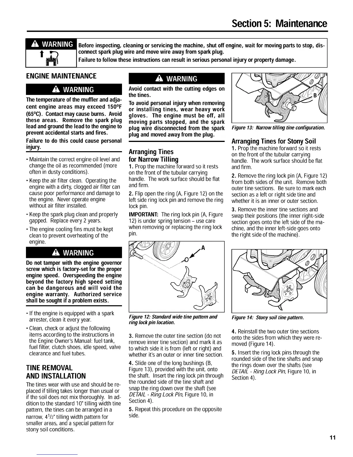
Avoid contactwith the cutting edges on
the tines.
To avoidpersonal injurywhen removing
or installing tines, wear heavy work
gloves. The engine must be off, all
moving parts stopped, and the spark
plug wire disconnectedfrom the spark
plugand movedaway from the plug.
ArrangingTines
for Narrow Tilling
1. Prop the machineforward so it rests
on the front of thetubular carrying
handle. The work surface should be flat
and firm.
2. Flipopen the ring (A, Figure12) on the
left sidering lock pin and removethe ring
lock pin.
IMPORTANT:Thering lock pin (A,Figure
12) is under spring tension - usecare
when removing or replacingthe ring lock
pin.
Figure13: Narrowtillingtineconfiguration.
Arranging Tines for Stony Soil
1. Prop the machineforward so it rests
on the front of the tubular carrying
handle. The work surface should be flat
andfirm.
2. Removethe ring lock pin (A, Figure12)
from both sides of the unit. Remove both
outer tine sections. Besure to mark each
section asa left or right side tine and
whether it is an inner or outer section.
3. Removethe innertine sections and
swap their positions (the inner right-side
section goesonto the left side of the ma-
chine, and the inner left-side goesonto
the right side of the machine).
• If the engine is equippedwith a spark
arrester,clean it everyyear.
• Clean,checkor adjust the following
items according to the instructions in
the EngineOwner's Manual:fuel tank,
fuel filter, clutch shoes, idle speed,valve
clearanceand fuel tubes.
TINE REMOVAL
AND INSTALLATION
Thetines wearwith useand should be re-
placedif tilling takes longer than usual or
if the soil does not mix thoroughly. In ad-
dition to the standard 10"tilling width tine
pattern,the tines canbe arranged in a
narrow, 41/2" tilling width pattern for
smaller areas,and a special pattern for
stony soil conditions.
Figure 12: Standardwide tinepattern and
ring lockpin location.
3. Removethe outer tine section (do not
remove inner tine section) and mark it as
to which side it is from (left or right) and
whether it'san outer or inner tine section.
4. Slide oneof the long bushings (B,
Figure13), provided with the unit, onto
the shaft. Insert the ring lock pin through
the rounded sideof the tine shaft and
snapthe ring down over the shaft (see
DETAIL- RingLock Pin,Figure10, in
Section 4).
5. Repeatthis procedure on the opposite
side.
Figure 14: Stonysoiltine pattern.
4. Reinstall the two outer tine sections
onto the sides from which they were re-
moved (Figure 14).
5. Insert the ring lock pins through the
rounded side of thetine shafts and snap
the rings down over the shafts (see
DETAIL- RingLock Pin,Figure10, in
Section 4).
11
 Loading...