!,'£4"4!1T_
2 Assembly
Topreventpersonalinjuryor propertydamage,do notstart
the engine until all assembly stepsare completeand you
haveread andunderstandthe safetyand operatinginstruc-
tionsin this manual.
INTRODUCTION
Carefullyreadthese instructions in their entirety beforeyou
attempt to assembleor operateyour newequipment.
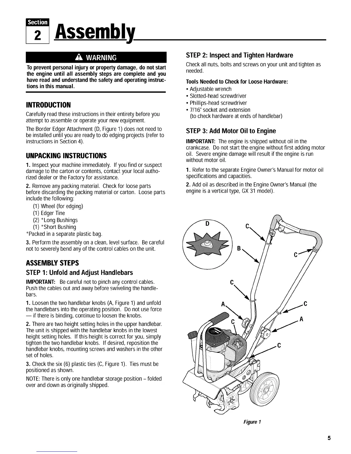
TheBorder EdgerAttachment (D, Figure1) doesnot needto
be installed until you are readyto do edging projects (referto
instructions in Section 4).
UNPACKINGINSTRUCTIONS
1. Inspect your machine immediately. If you find or suspect
damageto the carton or contents,contact your local autho-
rizeddealeror the Factoryfor assistance.
2. Removeany packing material. Checkfor loose parts
beforediscarding the packing material or carton. Loose parts
includethe following:
(1) Wheel(for edging)
(1) EdgerTine
(2) *Long Bushings
(1) *Short Bushing
*Packedin a separateplastic bag.
3. Perform the assembly on a clean, level surface. Becareful
not to severelybend anyof the control cables on the unit.
ASSEMBLYSTEPS
STEP 1: Unfold and AdJustHandlebars
IMPORTANT: Becareful not to pinch anycontrol cables.
Pushthe cablesout and awaybefore swivelingthe handle-
bars.
1. Loosen the two handlebarknobs (A, Figure 1) and unfold
the handlebarsinto the operating position. Do not useforce
-- if there is binding, continue to loosen the knobs.
2. Thereare two height setting holes in the upper handlebar.
Theunit is shipped with the handlebar knobs in the lowest
height setting holes. If this height is correct for you, simply
tighten the two handlebar knobs. If desired, reposition the
handlebarknobs, mounting screws and washersin the other
set of holes.
3. Checkthe six (6) plasticties (C, Figure 1). Ties must be
positioned as shown.
NOTE:Thereis only one handlebarstorage position - folded
over anddown asoriginally shipped.
STEP 2: Inspect and Tighten Hardware
Checkall nuts, bolts and screws on your unit and tighten as
needed.
ToolsNeededto Checkfor LooseHardware:
• Adjustable wrench
• Slotted-headscrewdriver
• Phillips-headscrewdriver
• 7/16"socket and extension
(to checkhardwareat ends of handlebar)
STEP 3: Add Motor Oil to Engine
IMPORTANT:Theengine is shippedwithout oil in the
crankcase. Do not start the engine without first adding motor
oil. Severeenginedamagewill result if the engine is run
without motor oil.
1. Referto the separate EngineOwner'sManualfor motor oil
specifications and capacities.
2. Add oil asdescribed in the EngineOwner's Manual(the
engine isa vertical type, GX31 model).
C
Figure 1
 Loading...