I,'£4"41t_
3 Featuresand Controls
KNOW YOUR EQUIPMENT
READTHISOWNER'SMANUALANDALL SAFETYRULESBEFOREOPERATINGYOUREQUIPMENT.Know the location and function
of all features and controls on the equipment. Savethis manualfor future reference.
Before operating your machine, carefully read and under-
stand all safety, control, and operating instructionsin this
Manual, the separate Engine Owner's Manual and on the
decalson themachine.
Failure to follow theseinstructions canresult in seriousper-
sonalinjury.
j G
D
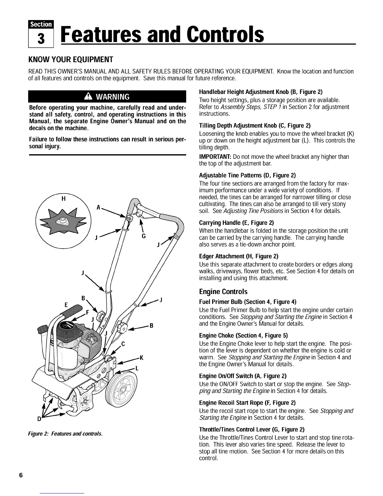
Figure2: Featuresandcontrols.
HandlebarHeightAdJustmentKnob(B, Figure2)
Twoheight settings, plus a storage position are available.
Referto Assembly Steps, STEP7in Section 2 for adjustment
instructions.
TillingDepthAdjustmentKnob(C, Figure2)
Looseningthe knob enablesyou to move the wheelbracket (K)
up or down on the heightadjustment bar (L). This controls the
tilling depth.
IMPORTANT:Donot movethe wheel bracketany higher than
thetop of the adjustment bar.
AdJustableTine Patterns(D, Figure2)
Thefour tine sections arearrangedfrom thefactory for max-
imum performance under a wide varietyof conditions. If
needed,the tines can bearranged for narrowertilling or close
cultivating. Thetines canalso be arrangedto till very stony
soil. SeeAdjusting TinePositions in Section 4 for details.
CarryingHandle(E, Figure2)
Whenthe handlebar isfolded in the storage position the unit
canbe carried bythe carrying handle. The carrying handle
alsoserves asa tie-down anchor point.
EdgerAttachment (H, Figure2)
Usethis separateattachmentto createborders or edgesalong
walks,driveways,flower beds,etc. SeeSection 4 for details on
installing and using this attachment.
Engine Controls
FuelPrimer Bulb(Section4, Figure4)
Usethe FuelPrimer Bulb to help start theengine under certain
conditions. SeeStoppingand Startingthe Enginein Section 4
and the EngineOwner's Manualfor details.
EngineChoke(Section4, Figure5)
Usethe EngineChoke leverto help start the engine. The posi-
tion of the lever is dependenton whether the engine is cold or
warm. SeeStoppingand Starting the Enginein Section 4 and
the EngineOwner'sManualfor details.
EngineOn/OffSwitch (A, Figure2)
Usethe ON/OFFSwitch to start or stop the engine. SeeStop-
ping and Starting theEnginein Section 4 for details.
EngineRecoil Start Rope(F, Figure 2)
Usethe recoil start ropeto start the engine. SeeStopping and
Starting theEngine in Section 4 for details.
Throttle/TinesControl Lever(G, Figure2)
Usethe Throttle/Tines Control Leverto start and stop tine rota-
tion. This leveralsovaries tine speed. Releasethe leverto
stop all tine motion. SeeSection 4 for more details on this
control.
 Loading...