NEO-8Q / NEO-M8 - Hardware Integration Manual
UBX-15029985 - R04 Production Information Hardware description
Page 10 of 31
Description including Protocol Specification [4]
1.5.6 TIMEPULSE2
On the NEO-M8T module, a configurable TIMEPULSE2 signal can be programmed on TP2/SAFEBOOT_N.
For more information, see the u-blox 8 / u-blox M8 Receiver Description including Protocol Specification [4]
The TIMEPULSE2 output must not be held LOW during start-up.
1.5.7 LNA_EN: LNA enable
On NEO-M8N, NEO-M8Q, NEO-M8T and NEO-8Q modules, in Power Save Mode, the system can turn on/off
an optional external LNA using the LNA_EN signal in order to optimize power consumption.
Signals: "high" = Turn ON LNA, "low" = Turn OFF LNA
1.6 Electromagnetic interference on I/O lines
Any I/O signal line with a length greater than approximately 3 mm can act as an antenna and may pick up
arbitrary RF signals transferring them as noise into the GNSS receiver. This specifically applies to unshielded lines,
in which the corresponding GND layer is remote or missing entirely, and lines close to the edges of the printed
circuit board.
If, for example, a cellular signal radiates into an unshielded high-impedance line, it is possible to generate noise
in the order of volts and not only distort receiver operation but also damage it permanently.
On the other hand, noise generated at the I/O pins will emit from unshielded I/O lines. Receiver performance
may be degraded when this noise is coupled into the GNSS antenna (see Figure 15).
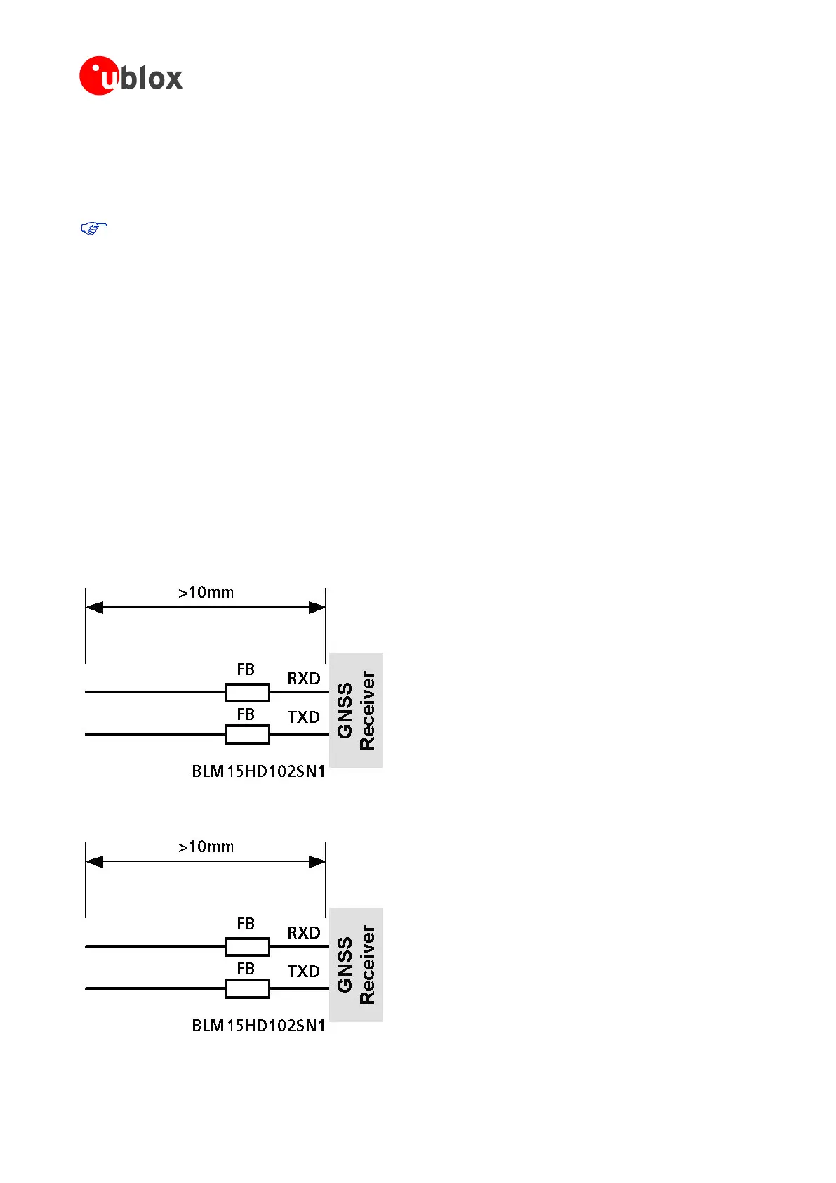
To avoid interference by improperly shielded lines, it is recommended to use resistors (e.g. R>20 ), ferrite beads
(e.g. BLM15HD102SN1) or inductors (e.g. LQG15HS47NJ02) on the I/O lines in series. These components should
be chosen with care because they will affect also the signal rise times.
Figure 3 shows an example of EMI protection measures on the RXD/TXD line using a ferrite bead. For more
information, see section 4.3.
Figure 3: EMI Precautions

 Loading...


