NEO-8Q / NEO-M8 - Hardware Integration Manual
UBX-15029985 - R04 Production Information Design
Page 13 of 31
2.2 Minimal design
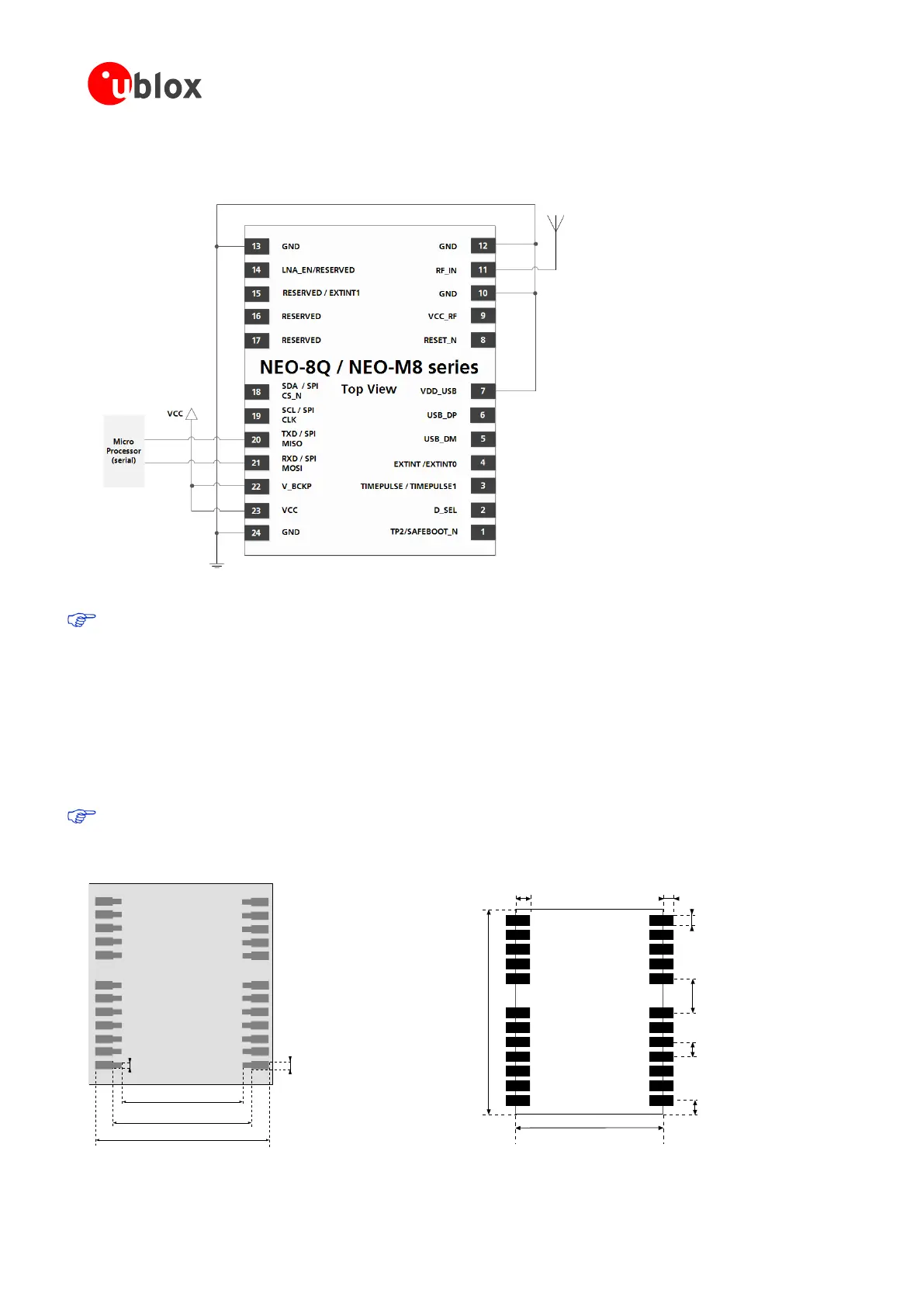
This is a minimal design for a NEO-8Q and NEO-M8 series GNSS receiver.
Figure 4: NEO-8Q / NEO-M8 passive antenna design
NEO-M8M can have a passive antenna, but for optimal operation requires an external SAW and LNA, see
Figure 7.
2.3 Layout: Footprint and paste mask
Figure 5 describes the footprint of the NEO-8Q and NEO-M8 series modules and provides recommendations (not
specifications) for the paste mask Note that the copper and solder masks have the same size and position.
To improve the wetting of the half vias, reduce the amount of solder paste under the module and increase the
volume outside of the module by defining the dimensions of the paste mask to form a T-shape (or equivalent)
extending beyond the copper mask. For the stencil thickness, see section 4.2.
Consider the paste mask outline when defining the minimal distance to the next component. The exact
geometry, distances, stencil thicknesses and solder paste volumes must be adapted to the specific
production processes (e.g. soldering) of the customer.
Stencil: 150
m
10.4 mm [409.5 mil]
14.6 mm [575 mil]
12.2 mm [480 mil]
0.8 mm
[31.5
mil
]
0.6 mm
[23.5
mil
]
Figure 5: NEO-8Q and NEO-M8 series paste mask NEO-8Q and NEO-M8 series footprint
12.2 mm [480.3 mil]
16.0 mm [630
mil
]
1.0 mm
[39.3 mil]
0.8 mm
[31.5
mil
]
0.8 mm
[31.5
mil
]
3.0 mm
[118.1
mil
]
1.0 mm
[39.3
mil
]
1.1 mm
[43.3
mil
]

 Loading...


