NEO-8Q / NEO-M8 - Hardware Integration Manual
UBX-15029985 - R04 Production Information Design
Page 14 of 31
2.4 Antenna
2.4.1 Antenna design with passive antenna
A design using a passive antenna requires more attention to the layout of the RF section. Typically, a passive
antenna is located near electronic components; therefore, care should be taken to reduce electrical noise that
may interfere with the antenna performance. Passive antennas do not require a DC bias voltage and can be
directly connected to the RF input pin RF_IN. Sometimes, they may also need a passive matching network to
match the impedance to 50 .
Use an antenna that has sufficient bandwidth to receive all GNSS constellations. See Appendix.
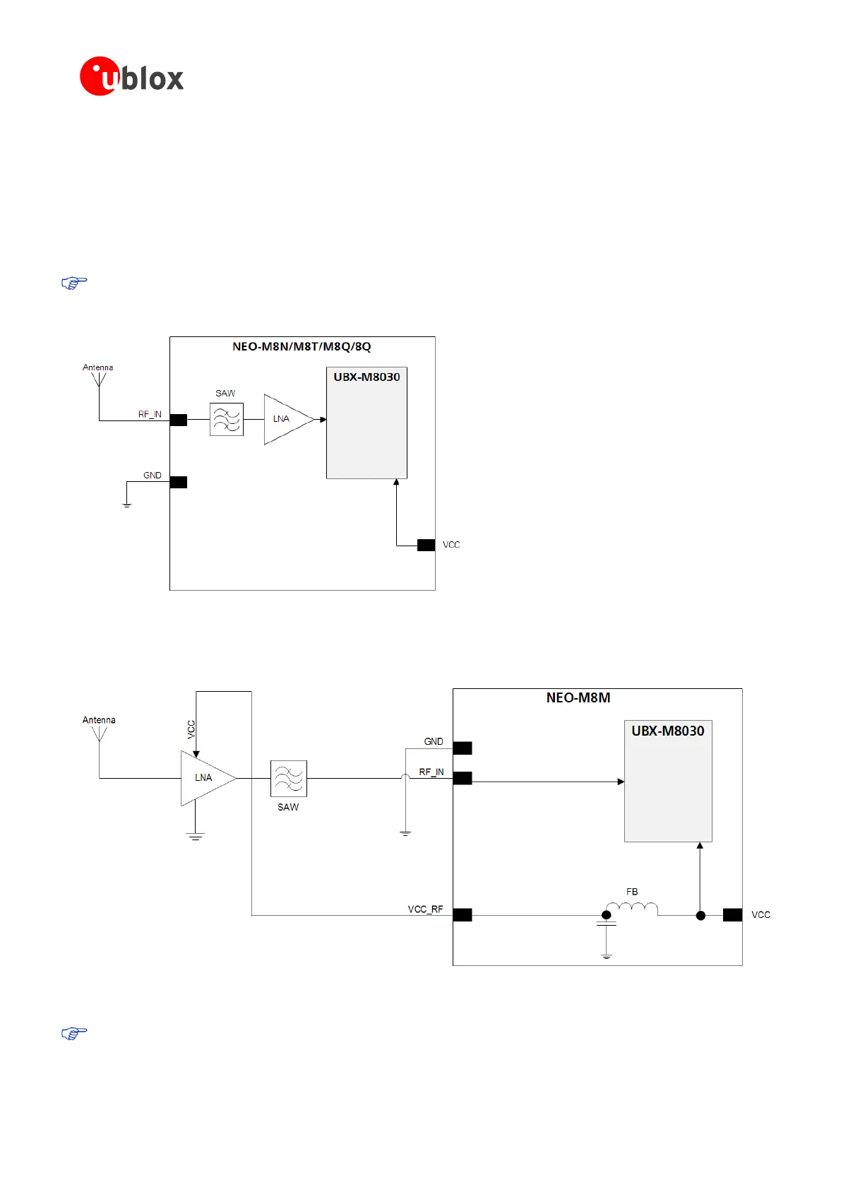
Figure 6 shows a minimal setup for a design with a good GNSS patch antenna. For exact pin orientation, see the
corresponding product data sheet in the Related documents.
Figure 6: NEO-M8N / NEO-M8T / NEO-M8Q / NEO-8Q passive antenna design
Figure 7 and Figure 8 show designs using an external LNA and SAW to increase the sensitivity for optimum
performance with passive antenna. For exact pin orientation, see the corresponding product data sheet in the
Related documents.
Figure 7: NEO-M8M module design with passive antenna and an external LNA and SAW
The VCC_RF output can be used to supply the LNA with a filtered supply voltage.
An external LNA is only required if the antenna is far away. In that case, the LNA must be placed close to
the passive antenna.

 Loading...


