19
2. Set the rotary switch to V
;
to select AC measurement mode.
3. Connect the test leads across with the object being
measured.
The measured value shows on the display.
and press BLUE button
Note
l In each range, the Meter has an input impedance of
10MΩ. This loading effect can cause measurement
errors in high impedance circuits. If the circuit
impedance is less than or equal to 10kΩ, the error is
negligible (0.1 or less).
l When AC voltage measurement has been completed,
disconnect the connection between the testing leads
and the circuit under test and remove testing leads
from the input terminals.
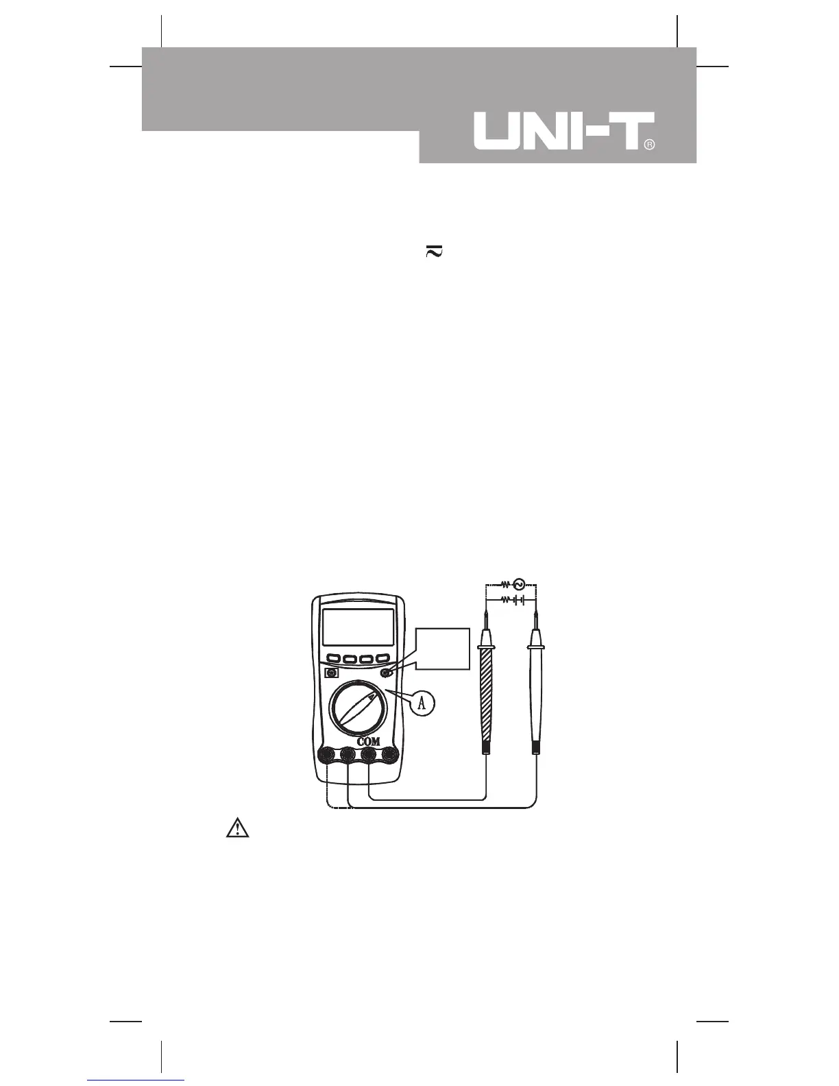
C. DC or AC Current Measurement (see figure 5)
red
Select
DC or AC
black
( figure 5)
Warning
If the fuse burns out during measurement, the Meter
may be damaged or the operator himself may be hurt.
Use proper terminals, function and range for the
measurement. When the testing leads are connected
to the current terminals, do not parallel them across
any circuit.
Measurement Operation(3)
Model UT60F/G: OPERATING MANUAL
 Loading...