1
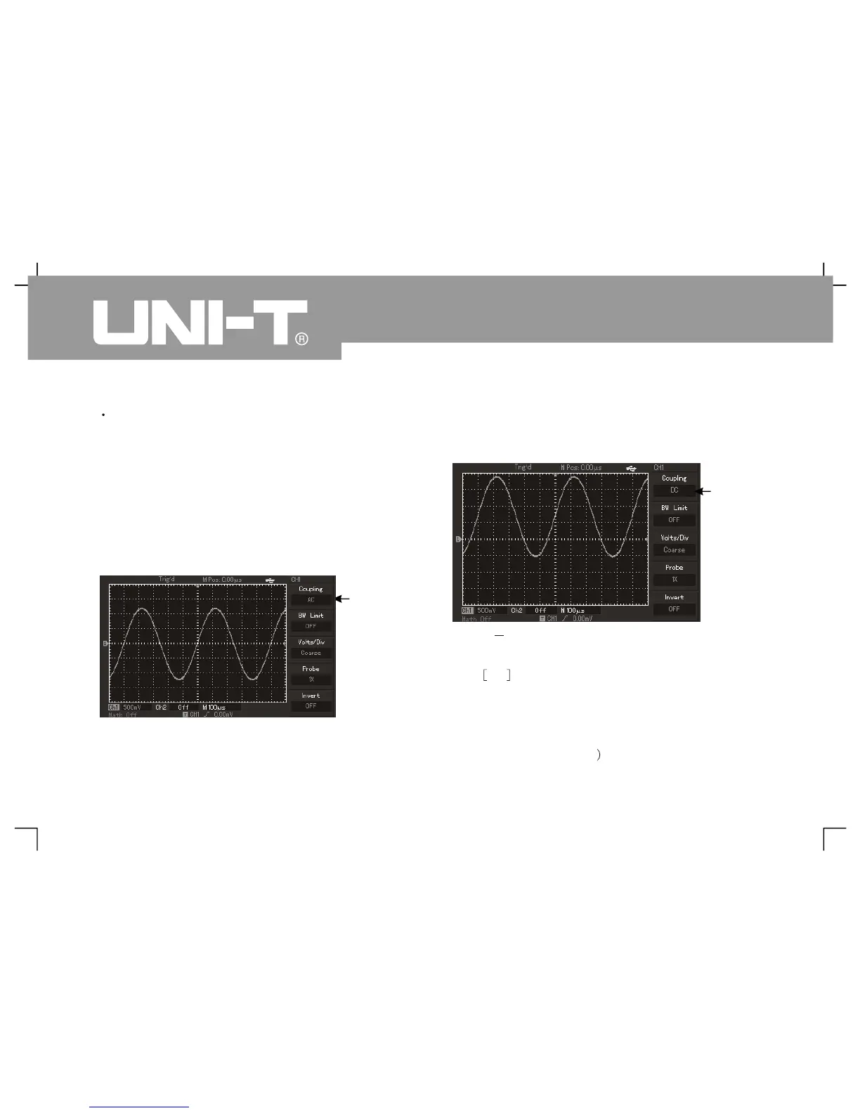
Measured signal is a sine signal with DC component
by taking exerting signal to CH1 channel as a
To press F1 to select AC and AC coupling mode. D
component contained by measured signal will be
obstructed. Waveform display is s hown in followin
Press F1 to DC to pass through DC and A
components of measured signals of CH1 channel
Waveform display is also shown in following figure
Figure 2 2 Synchronous display of DC and A
components of signal
Press F1 to select grounding and s et channels to
grounding mode. DC and AC components
contained by measured signals will be obstructed.
Waveform display is shown in following figure
Oper ating Man ual fo r UTD 2000/3000
Figure 2 Jammed DC component of signal㧙1
Setup of
 Loading...

