Section 1 - General Information Electric Motors
Service Manual Page 1-11
I
NSPECTION
Once the motor has been disassembled, go through the following check-list steps to determine where the
problem lies.
1. Bearings should spin smoothly and easily and have ample lubrication and be free of corrosion.
2. The armature should be checked for grounds and shorted turns. Re-finish the commutator surface if it is
pitted or excessively worn. (This procedure should be performed by a qualified electric motor shop.)
3. Brushes should be checked for wear and to ensure that they are free in the brush holders.
NOTE:
Observe how the brushes are assembled in the brush holders, and the position of the brush lead. New brushes
must be installed in the same manner. Brushes should be removed as follows:
a. Remove the brush spring clip from its mounting on the brush assembly.
b. Lift the brush assembly from the brush holder.
c. Disconnect the brush assembly lead.
d. Install the new brush assembly by reversing the above procedure.
4. Inspect the wire harness and all connections for signs of damage due to overheating.
5. Check the stator to see if it is securely mounted.
R
EASSEMBLY
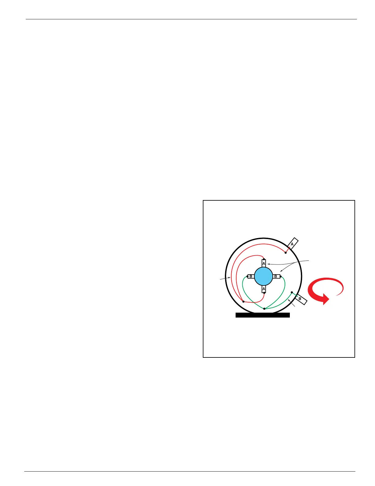
Figure 1-7:
Electric Motor Brushes
1. Install new brushes and be sure they are free
in the holder. Install the brush with the lead
wires positioned as when received. Raise all
brushes to the locked position. (See
Figure 1-7 and
Inspection
Step 3.).
2. Place the commutator cover on a work bench
with the brush assembly facing upward.
3. Place the bearing spring into the bearing bore.
4. Take a complete armature assembly, including
bearings, and insert the commutator end
bearing into the bearing bore.
NOTE:
Do not re-use bearings which have been removed
from the armature shaft. Keep the assembly in a
vertical position. Use extreme care not to damage
the armature with bearing pullers. New bearings
should be installed by pressing the inner race of the
bearing onto proper position on the armature shaft.
5. Set the brushes into their final position as
shown in Figure 1-7.
6. Place the complete stator down over the vertical armature, and into position on the commutator cover.
7. The stator assembly must be placed in a definite relationship with the commutator covers in order to
obtain a neutral brush setting. There is a match-mark on both items. These two marks must line up
exactly. Rotate until they do.
8. Assemble the pulley end cover in the proper relationship. Insert the mounting bolts and tighten alter-
nately to ensure a good mechanical alignment.
9. Spin the shaft by hand to see if it is free. Be sure motor leads (if used) are not touching together. If the
leads are touching, a generator action will give the effect of friction in the motor. A no-load test can now
be performed. At the rated voltage, observe the no-load current. It should be less than 20% of the name-
plate full load current. Anything higher indicates:
• Brushes are not on neutral setting (check match-marks for exact alignment).
• Faulty armature.
Counterclockwise
Rotation
Buss Bar
Brushes
Buss Bar
Typical pump motor viewed from rear.
Brushes and
springs in their
final position
Brushes raised with
the springs in locked
position on the side
of the brush
NOTE:
This illustration is a 015797-011 pump motor.
Other electric motors may rotate in either direction,
and may use only two brushes.

 Loading...


