Sensors Section 2 - Service and Repair
Page 2-24 107099-002 TM12 Work Platform
P
ROXIMITY
S
WITCH
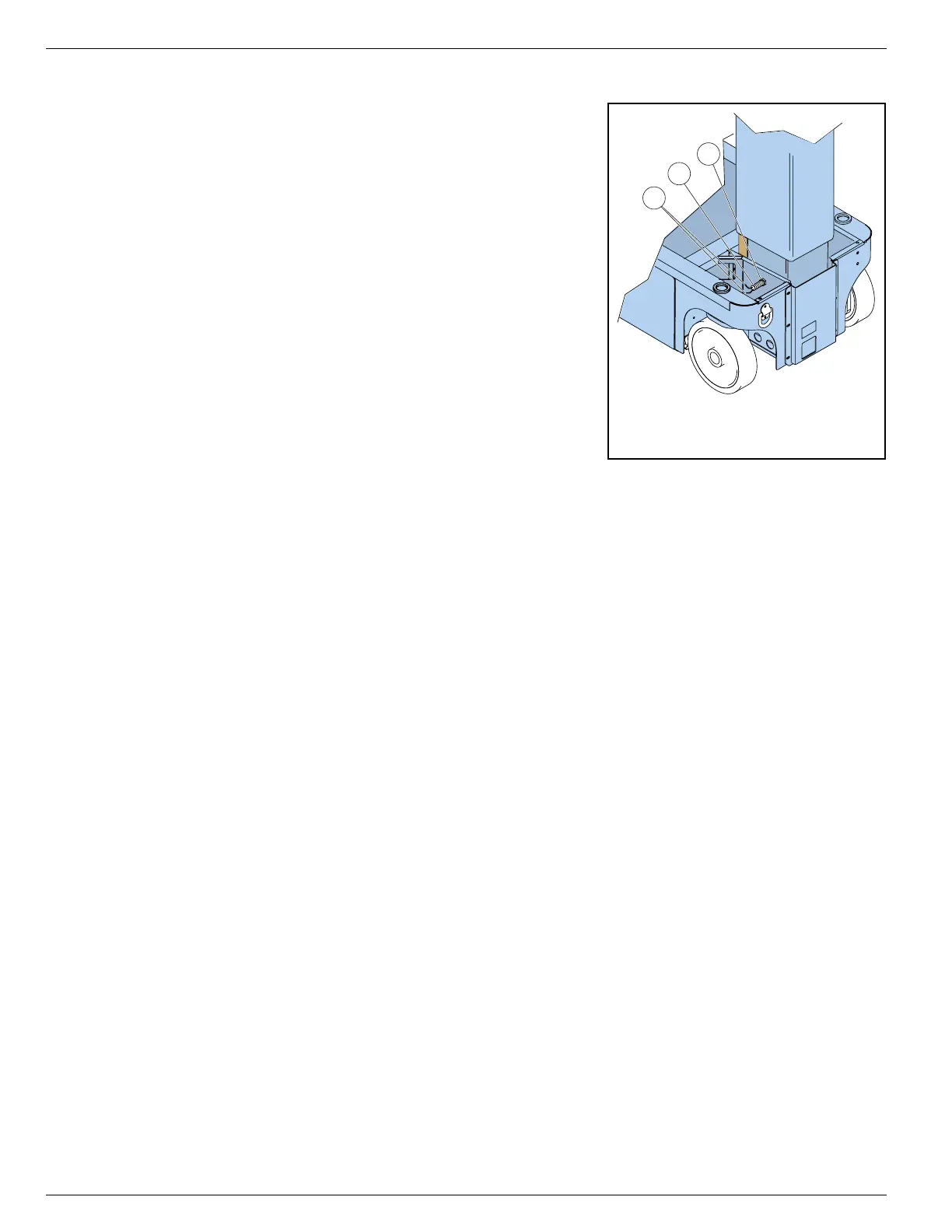
Figure 2-19:
Proximity Switch
The Proximity Switch is located under the top chassis cover on
the front right side.
P
ROXIMITY
S
WITCH
F
UNCTION
The Proximity Switch controls the machine operation.
Platform Elevated:
• The switch is open.
• The Level Sensor is enabled.
• Power to the High Speed Circuit is cut, preventing the
machine from travel faster than 0,8 km/h (
0.5 mph
).
Platform Lowered:
• The switch is closed.
• Power is supplied to the High Speed Circuit, allowing the
machine to travel up to 3,2 km/h (
2.0 mph
) when the Plat-
form Controls Drive Speed Switch is set to HI SPEED.
T
EST
THE
P
ROXIMITY
S
WITCH
1. Place the machine on a firm, level surface.
2. Support the elevating assembly (see “Supporting Elevating Assembly” on page 2-3).
3. Remove the chassis top cover.
4. Disconnect the switch leads and connect a multimeter to the switch.
• The switch should be OPEN, and the multimeter should read no continuity.
5. Remove the elevating assembly support and fully lower the work platform.
• The switch should be CLOSED, and the multimeter should read continuity.
• If the multimeter reads no continuity, replace the switch.
6. Support the elevating assembly (see “Supporting Elevating Assembly” on page 2-3).
7. Install the top cover to the chassis.
8. Remove the elevating assembly support and fully lower the work platform.
R
EMOVE
1. Place the machine on a firm, level surface.
2. Support the elevating assembly (see “Supporting Elevating Assembly” on page 2-3).
3. Remove the top cover from the chassis.
4. Disconnect the switch leads.
5. Remove the outer adjustment nut from the side of the switch that faces the mast and remove the switch.
I
NSTALL
1. Position the switch in the hole in the chassis and thread the outer adjustment nut onto the switch until
the face of the switch is flush with the adjustment nut.
2. Tighten the inner adjustment nut securely.
3. Connect the switch leads.
4. Install the chassis top cover.
5. Remove the elevating assembly support and fully lower the work platform.
1 Proximity Switch
2. Adjustment Nuts
3. Switch Leads

 Loading...


