Section 2 - Service and Repair Cylinders
107099-002 TM12 Work Platform Page 2-17
L
IFT
C
YLINDER
R
EMOVAL
Refer to Figure 2-16: “Elevating Assembly,” on page 2-19 for details.
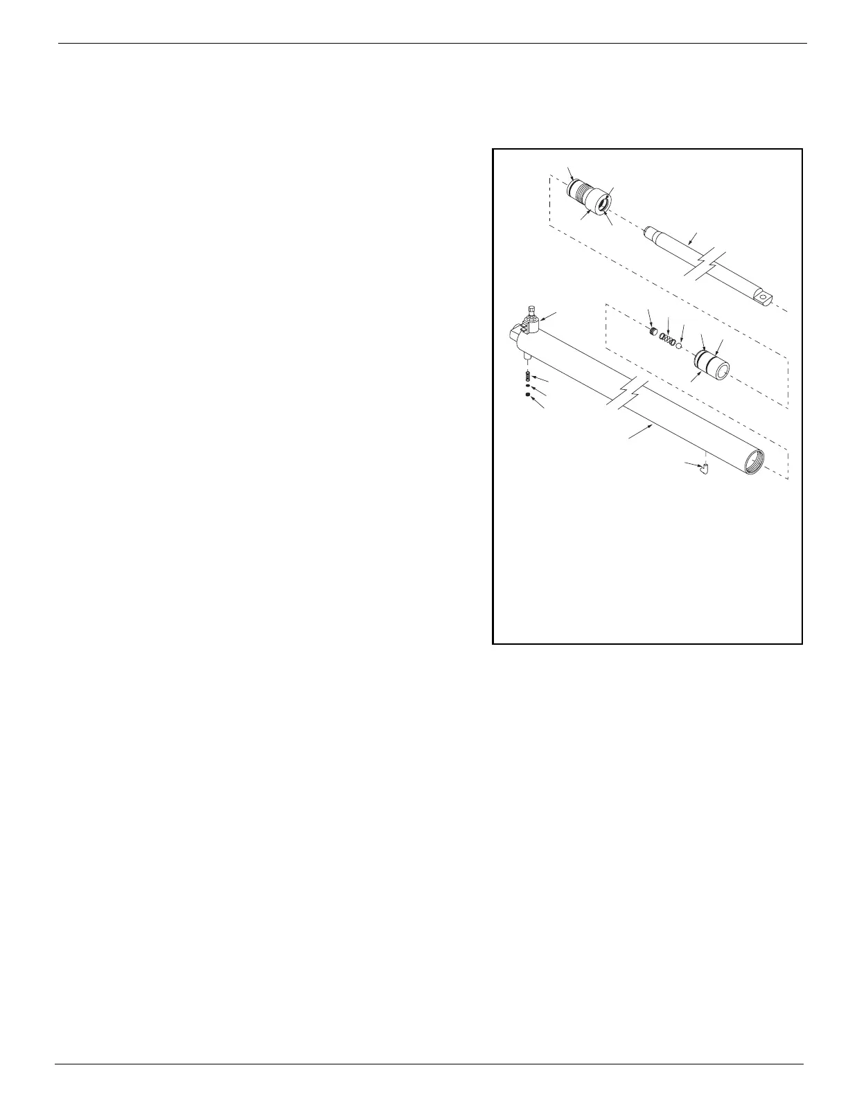
Figure 2-14:
Lift Cylinder Seal Kit
1. Fully lower platform.
2. Provide a suitable container to catch the hydraulic
fluid, then disconnect the hydraulic hose. Immedi-
ately plug hoses to prevent foreign material from
entering.
3. Remove the adapter from the base of the cylinder,
inside the chassis.
4. Remove the Emergency Lowering Valve Knob from
the valve at the base of the cylinder, then remove
the Emergency Lowering Valve out the access hole
in the bottom of the chassis.
5. Remove the snap ring at the bottom of the cylinder
under the chassis.
6. Detach the 6,35 mm (
0.25 in.
) vent line tubing from
the top of the hydraulic tank, and cut any plastic ties
that secure the tubing. Plug the end of the tubing to
prevent contamination.
7. Remove the platform mast cover.
8. Remove the capscrew and locknut securing the cyl-
inder rod to the upper cylinder mount.
9. Attach a suitable hoisting device and sling to the
cylinder. Carefully lift the cylinder approximately
0,5 m (
18 in.
) until you can see the vent line tubing
attached near the top of the cylinder barrel. Detach
the tubing by depressing the green ring on the fitting
at the same time you pull firmly on the tube. Plug
the end of the tube and the fitting to prevent con-
tamination.
10. Raise the cylinder the rest of the way through the top of the mast.
R
EPAIR
Refer to Cylinder Repair in Section 1 - General Information.
I
NSTALLATION
1. Attach a suitable hoisting device and sling to the cylinder. Carefully lower the cylinder through the top of
the mast until you can reattach the vent line tubing. Simply push the tubing into the fitting until it goes no
further. Pull firmly to ensure that it is installed correctly.
2. Lower the cylinder the rest of the way, and secure the cylinder to the chassis with the snap ring.
3. Install capscrew, washers and locknut securing cylinder rod to the upper cylinder mount.
4. Install platform mast cover.
5. Install the Emergency Lowering Valve, Knob and adapter to the base of the lift cylinder.
6. Remove the plug from the hydraulic hose and attach it to the adapter.
7. Attach the vent line to the hydraulic tank.
8. Test with weight at rated platform load to check system operation. Check for leaks
1. Rod
2. Cylinder Barrel
3. Headcap
4. Piston
5. Ball Bearing, 3/8”
6. Spring
7. Set Screw, Allen Head
8. 90° Fitting
9. Emergency Lowering
Valve
10. Orifice Spring
11. Orifice, 0.063”
12. Spacer
Seal Kit Includes:
A. Piston Seal
B. Piston Seal
C. Static Seal
D. Rod Seal
E. Rod Wiper

 Loading...


