Section 2 - Service and Repair Hydraulics
107099-002 TM12 Work Platform Page 2-11
M
AIN
H
YDRAULIC
M
ANIFOLD
Though it is not necessary to remove the manifold to perform all maintenance procedures, a determination
should be made prior to beginning as to whether or not the manifold should be removed before mainte-
nance procedures begin.
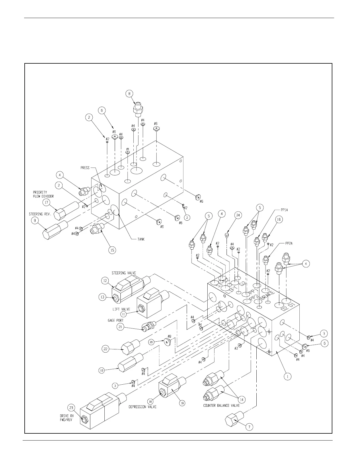
Figure 2-8:
Hydraulic Manifold, Exploded View
1. Control Valve Block
2. Fitting, #2 Plug
3. Fitting, #4 Plug
4. Fitting, Straight 6MB - 6MJ
5. Fitting, Straight 4MB - 6MJ
6. Fitting, #6 Plug
7. Plug Cavity, #8 2-way
8. Fitting, 8MB - 6MJ
9. Relief Valve, Steering
(103,4 bar [1500 psi])
10. Relief Valve, Main
(206,8 bar [3000 psi])
11. Lift Valve
2-Position - 4-Way Solenoid
with Coil
12. Coil
13. Steering Valve
3-Position - 4-Way Solenoid
with Coils
14. Counterbalance Valve
15. Fitting, Straight 8MB - 4MJ
16. Fitting 4MB - 4MJ with orifice
(0.079 mm [0.031 in.])
17. Priority Flow Divider Valve
(3,8 lpm [1 gpm])
18. Depression Valve
2-Position Poppet Valve With
Coil
19. Coil
20. Fitting, #8 Plug
21. Fitting Gage Port
22. Check Valve
23. Drive RV Forward/Reverse
Valve
3-Position - 4-Way Solenoid
with Coils
24. Fitting, Plug #4

 Loading...


