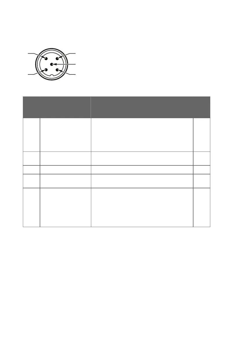
4.1 Wiring
Figure 7 Probe M12/5 Pins
Pin # Function Notes Wire
Color
1)
1 Power supply With digital output: 15 ... 30 VDC
With analog output: 15 ... 25 VDC
When using analog outputs, it is recommended to
use a low supply voltage to minimize self-heating
and maximize measurement performance.
Brown
2 RS-485- or analog
output 2
Current output: 4 … 20 mA (default).
2)
White
3 Power and signal GND Blue
4 RS-485+ or analog
output 1
Current output: 4…20 mA (default)
2)
Black
5 Output control and purge
trigger in analog mode
Floating = RS-485
Grounded = Analog outputs
If you want to be able to trigger a purge manually in
the analog mode, do not connect pin #5
permanently to ground, but instead, use a relay or
similar to control the pin.
Grey
1) Wire colors apply to the following cables: 223263SP, 26719SP, 26720SP, 216546SP,
244669SP
2) The ordered parameters and scaling are shown in the calibration certificate delivered with
the probe.
HPP272 User Guide M211972EN-B
22

 Loading...