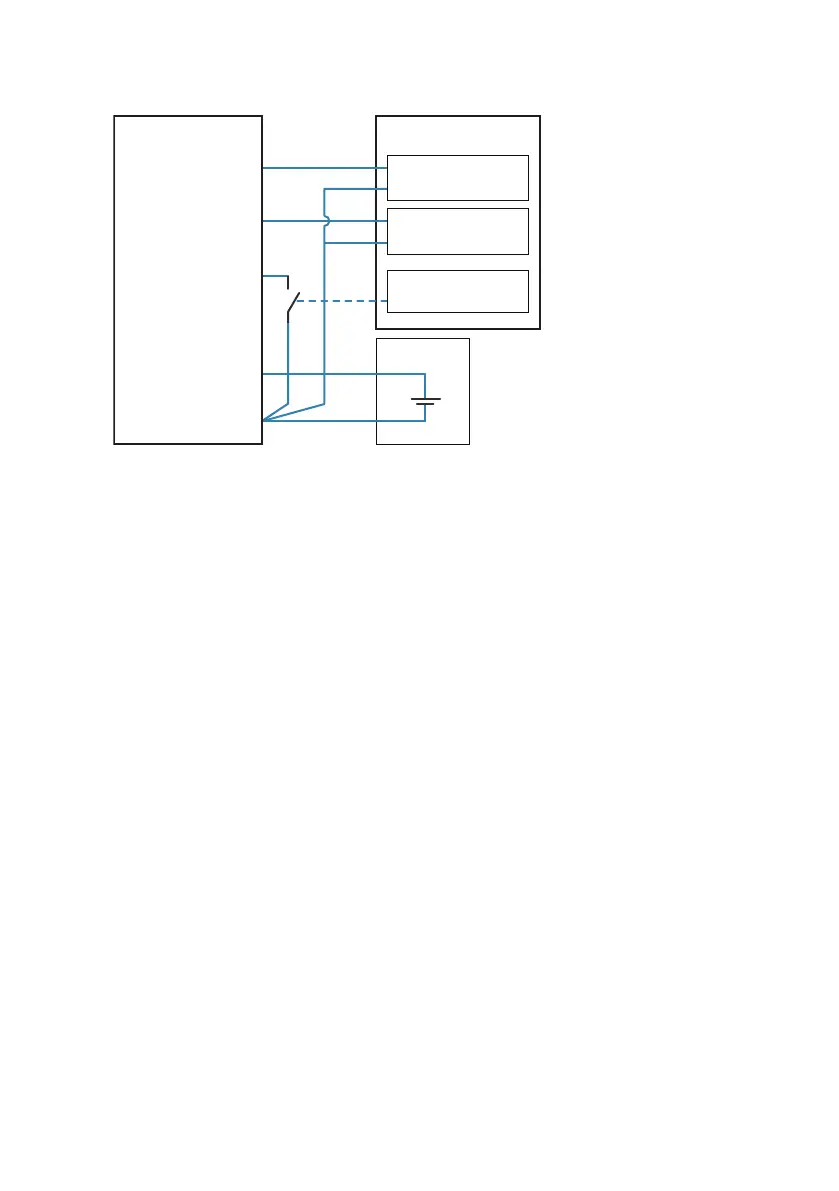
PLC
DC power
supply
IN+ Current input
IN-
IN+ Current input
IN-
Relay/switch
control
+
-
Pin #1
(Power supply)
Pin #2
(Analog output 2)
Pin #3
(Power and signal
GND)
Pin #4
(Analog output 1 )
Pin #5
(Output control
and purge trigger
in analog mode)
HPP270 series
probe
Figure 8 Wiring Example for Connecting HPP272 to a PLC in Analog Mode
More Information
‣
Accessories (page 44)
‣
Triggering Purge in Analog Mode (page 27)
4.2
Power Supply
Operating voltage range of the probe:
• With digital output: 15 ... 30 VDC
• With analog output: 15 ... 25 VDC
Maximum current consumption at 25 °C:
• With digital output: 15 mA
• With analog output: 50 mA
• During purge: 200 mA
4.3
Setting Probe in Analog or Digital Mode
The probe has two output modes: digital mode (RS-485 using Modbus) and analog mode
(current output).
Both the digital output and analog output use the same pins in the M12 male connector (pins
#2 and #4), but only one of the output modes can be active at the same time. You select which
output mode is active with the output control pin #5.
Chapter 4 – Installation
23

 Loading...