Doc: 70-00-0792B V1.3, 20220830 © Vector Controls GmbH, Switzerland Page 12-34
Subject to change without notice www.vectorcontrols.com
4.2 Selection of actuators and sensors
Temperature sensors:
Use Vector Controls NTC sensors to achieve maximum accuracy, see ordering list in chapter 1.3, page 3.
Binary auxiliary devices (e.g. fans, on/off valves, etc.):
Do not directly connect devices that exceed specified limits in technical specifications – observe startup current on
inductive loads.
4.3 Electrical connection of external inputs
Use only twisted pair copper conductors for input connections. The operating voltage must comply with the requirements
for safety extra-low voltage (SELV) as per EN 60 730.
4.4 Power Failure
All temperature set points and parameters are automatically saved and do not need to be re-entered.
4.5 Modbus wiring (TRA-F121-A only)
4.5.1 Wire type
An EIA-485 network shall use shielded, twisted-pair cable for data signaling with characteristic impedance between 100
and 130Ω s. Distributed capacitance between conductors shall be less than 100 pF per meter (30 pF per foot). Distributed
capacitance between conductors and shield shall be less than 200 pF per meter (60 pF per foot). Foil or braided shields
are acceptable.
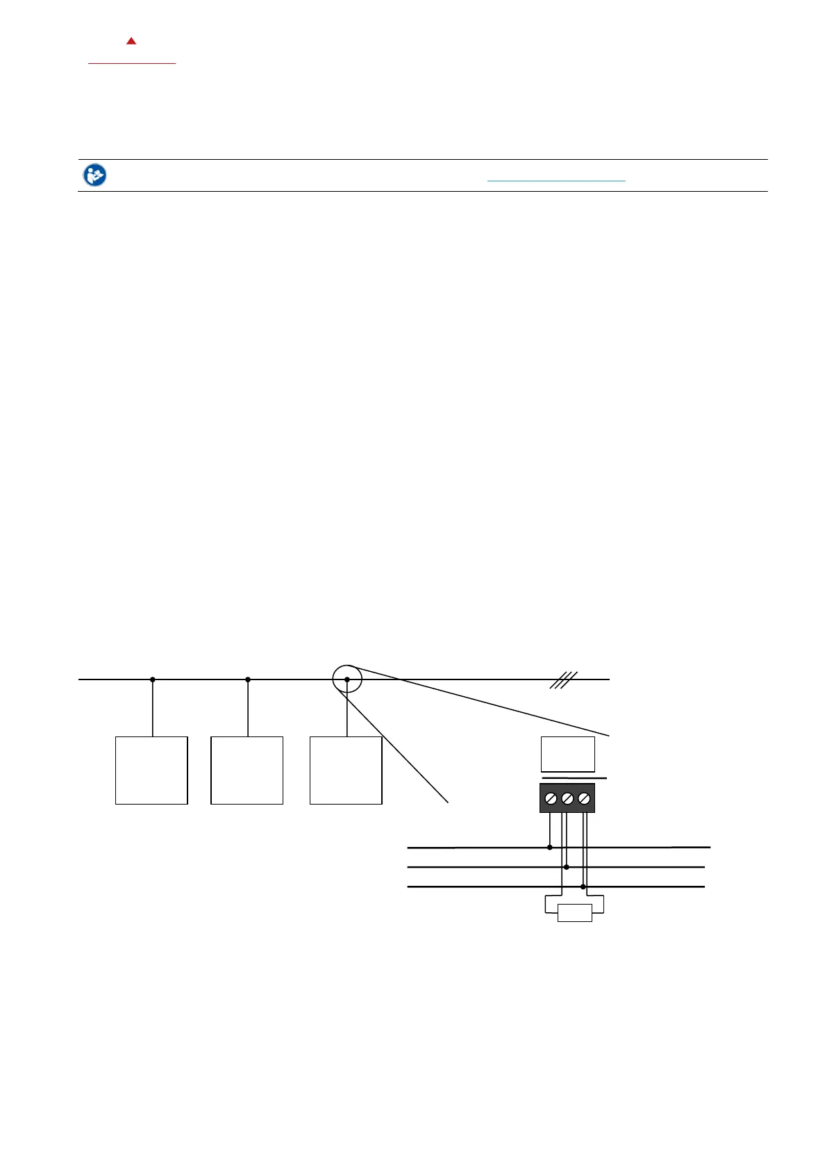
4.5.2 Line termination
On last node on either end of the bus connect a 120Ω termination resistor between (+) and (-).
4.5.3 Maximum length
The maximum recommended length per segment is 1200 meters (4000 feet) with AWG 18 (0.82 mm2) conductor area
cable.
4.5.4 Shield connection
See Ashrae Standard 135 for detailed recommendation regarding how to connect the shield depending on type of nodes
present in the network.
4.5.5 Communication wiring
 Loading...