Doc: 70-00-0792B V1.3, 20220830 © Vector Controls GmbH, Switzerland Page 8-34
Subject to change without notice www.vectorcontrols.com
3.2.3 Large and small digits
The large digits show the measured room temperature (default setting) or the Comfort temperature set point
(configurable via parameter P101).
The small digits are off (default setting) or show the outdoor temperature from Modbus master (configurable via
parameter P101). Also, alarms and error messages are shown on the small digits.
The room temperature and temperature set point are given in °C or °F (according to parameter P102).
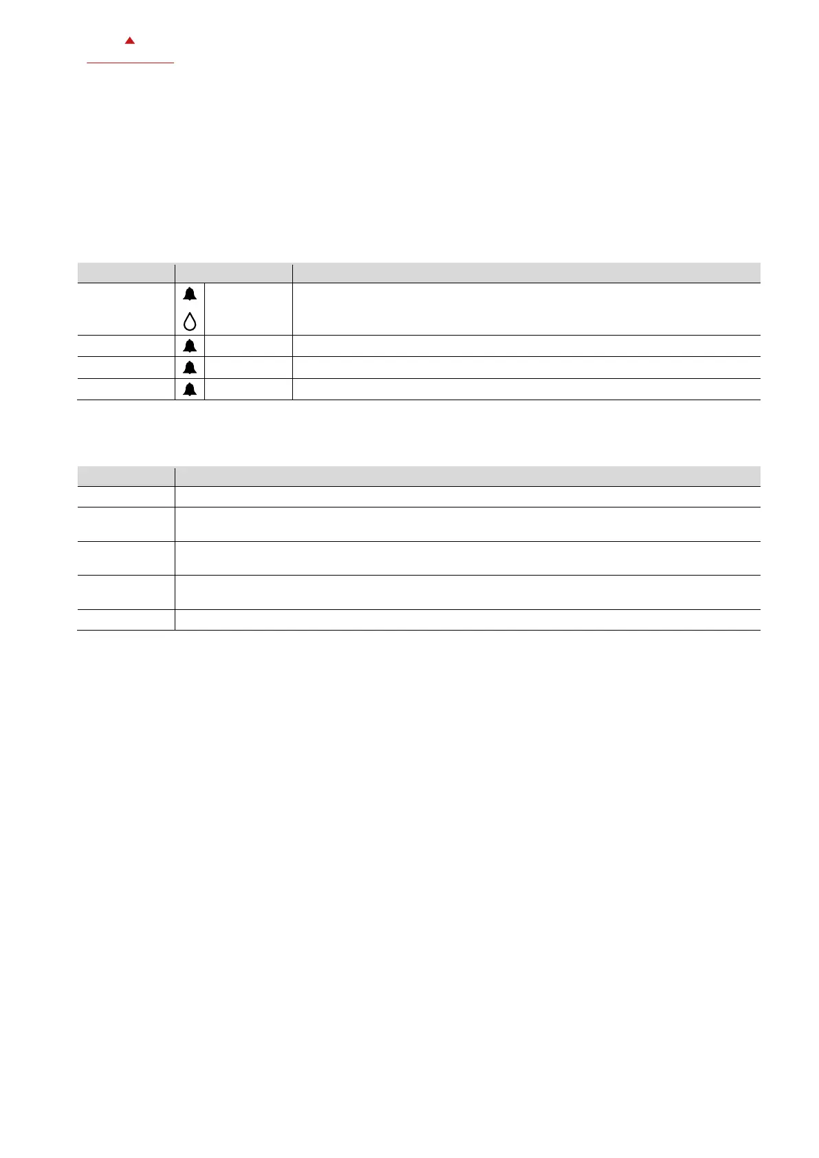
3.2.4 Alarm messages
Alarm messages with alarm symbol are shown on the small digits.
Dew point alarm from input RT1/2 (parameter P500/P502 = 7)
Overheat protection alarm (only in Protection mode)
Frost protection alarm (only in Protection mode)
Electric heater overheat alarm
3.2.5 Error messages
Error messages are shown on the small digits.
Built-in temperature sensor error. Sensor is damaged (open or short circuit).
Temperature sensor RT1/RT2 error. The temperature sensor is not present. Verify wiring or parameter
configuration. -99.9 is shown on large digits.
Digital input error. RT1/2 is not fully opened or closed (resistor between 2.5kΩ and 350kΩ). Verify
wiring or parameter configuration.
Configuration error: A parameter is set in an invalid combination with another parameter. Err4 and
one of the conflicting parameters are displayed alternating.
Time error: Set time and acknowledge error.
3.3 Temperature control
The thermostat measures the room temperature via built-in sensor or external room temperature sensor and maintains
the set point temperature by controlling the fan speeds and the heating and/or cooling valve (or the electric heater). The
following control outputs are available:
• on/off valve
• 3-position valve (only for 2-pipe systems)
The switching differential or proportional band is 2°C for heating mode and 1°C for cooling mode (configurable via
parameters P400 and P401).
The integral time is 5 minutes (adjustable via parameter P402 with 300 seconds as default value).
 Loading...