Doc: 70-00-0792B V1.3, 20220830 © Vector Controls GmbH, Switzerland Page 19-34
Subject to change without notice www.vectorcontrols.com
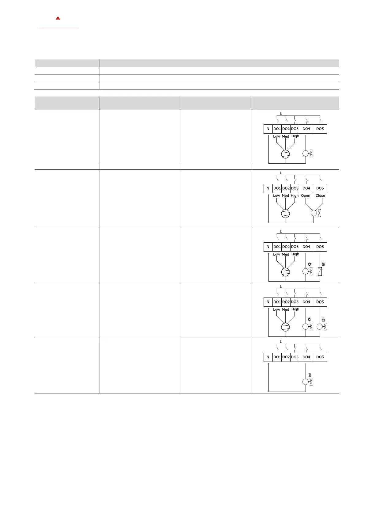
5.6.3 Application modes: Wiring diagrams of outputs
Valve type of heating/cooling system
P200, P201, P203
settings
Wiring diagram of outputs
• 2-pipe system
• on/off valve
• DO4: Heating or cooling
Manual heating or cooling
3-stage fan
Automatic heating or cooling
3-stage fan
• 2-pipe system
• 3-position valve
• Heating or cooling
• DO4 open valve
• DO5 close valve
Manual heating or cooling
3-stage fan
Automatic heating or cooling
3-stage fan
• 2-pipe system cooling
only with electric heater
• on/off cooling valve
• DO4: Cooling
• DO5: Electric Heater
Cooling with electric heater
3-stage fan
1 = ON = Electric
heater enabled
• 4 pipe system
• on/off valve
• Heating and/or cooling
• DO4: Cooling
• DO5: Heating
Manual heating or cooling
3-stage fan
Auto heating or cooling
RT1 as normally open DI
3-stage fan
Heating and cooling
3-stage fan
• Floor heating system
• on/off valve
• DO4: Heating
Floor heating
On/off valve
 Loading...