Doc: 70-00-0792B V1.3, 20220830 © Vector Controls GmbH, Switzerland Page 30-34
Subject to change without notice www.vectorcontrols.com
6 Runtime Data
6.1 Resolution and data format
All temperature related data are given in °C for Modbus. Only in the user interface values can be shown in °F.
Data without multiplier have resolution 1. Data with multiplier 10 have resolution 0.1.
For example, the default value of Comfort temperature set point (P300) is 20.0°C and the value read via Modbus is 200
(because of multiplier 10 used for P300).
Data with values below 0 (zero) are given as signed integer values.
6.2 Modbus access
The controller supports the following Modbus function cods:
Read multiple register (0x03)
Read n registers (n x 2 bytes) starting from requested address.
Write 1 register (2 bytes) at requested address.
Write multiple registers (0x16)
Write n register (n x 2 bytes) starting from sent address.
Note: The read/write capability of each data element is defined in column “R/W”. Most data can be read and written
defined as “R/W”. Read only data are defined as “R”.
6.3 Address table of controller runtime data
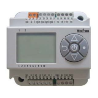
Vector product series information
Controller software version
Controller software revision
0 = No alarm
1 = Dew point alarm from RT1/2 (P500/502 = 7)
2 = Overheat protection alarm
3 = Frost protection alarm
0 = No error
1 = Built-in temperature sensor error
2 = Temperature sensor RT1/RT2 error
3 = Digital input is not open/close
4 = Configuration error
5 = Time error (time not set)
0 = Comfort
1 = Economy
2 = Protection
0 = Heating
1 = Cooling
2 = Fan only
0 = Fan off
1 = Low Fan
2 = Mid Fan
3 = High Fan
0 = Automatic
1 = Manual (set to manual if fan speed value
changed from Modbus master)
Room temperature (Built-in
sensor)
Multiplier: 10; Integer (signed)
-20.0…60.0 °C (-4.0…140 °F)
-100.0 (= 0xFC18) = Sensor damaged
Multiplier: 10; Integer (signed)
-20.0…60.0 °C (-4.0…140 °F)
-100.0 (= 0xFC18= = none (digital input)
Multiplier: 10; Integer (signed)
-20.0…60.0 °C (-4.0…140 °F)
-100.0 (= 0xFC18) = none (digital input)
 Loading...