11
5 Connecting to power supply
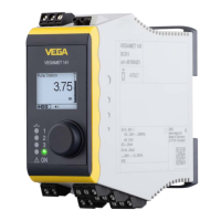
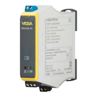
VEGATOR 141 •
46838-EN-210714
•
In active mode, VEGATOR 141 provides the power for the con-
nected sensors. Power and measurement data are transmitted
over the same two-wire cable. This mode is provided for connec-
tion of measuring transducers without separate power supply
(sensors in two-wire version).
•
In passive mode, the sensors are not powered, only the meas-
ured value is transmitted. This input is provided for connection of
transducers with their own separate voltage supply (sensors in
four-wire version). Furthermore the VEGATOR 141 can be looped
like a standard ammeter into the existing circuit. It is thus possible
tocontrolmultiplecontrollerswithonesensortodetectdierent
limit levels.
Note:
With a VEGATOR 141 in Ex version, the passive input is not available
for reasons of approval.
5.3 Connection procedure
The pluggable terminals can be removed as needed to allow more
convenient connection. To make the electrical connection, proceed as
follows:
1. Mount the instrument as described in the previous chapter
2. Connect sensor cable to terminal 1/2, and where applicable, con-
nect the shielding
3. Connectswitched-opowersupplytoterminal16/17
4. Connect relay to terminal 10/11/12
5. Option with fail safe relay: Connect relay to terminal 13/14/15
Theelectricalconnectionisnished.
 Loading...