12
5 Connecting to power supply
VEGATOR 141 •
46838-EN-210714
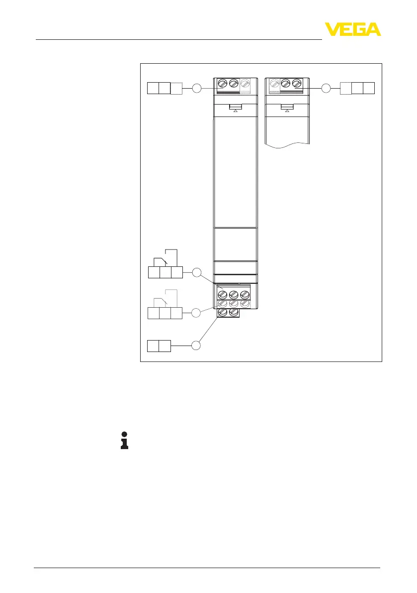
5.4 Wiring plan
1
3
5
4
2
10 11 12
13 14 15
-+
16 17
-+
1 2
-+
2 3
OPEN OPEN
Fig. 1: Wiring plan VEGATOR 141
1 Sensor circuit (4 … 20 mA), active input
2 Sensor circuit (4 … 20 mA), passive input
1)
3 Relay output
4 Fail safe relay (optional)
5 Voltage supply
Information:
The connection terminals can be detached towards the front, if
necessary. This can be useful when working in tight spaces or when
exchanging an instrument.
5.5 Connection example, mixed operation active/
passive
With this wiring, one sensor can control several controllers and thus
detectdierentlimitlevels.ThiswiringisnotpossibleforExapplica-
tions, as the passive input is not available for Ex devices.
1)
Not available with Ex version.

 Loading...