18
6 Setup
VEGATOR 141 •
46838-EN-210714
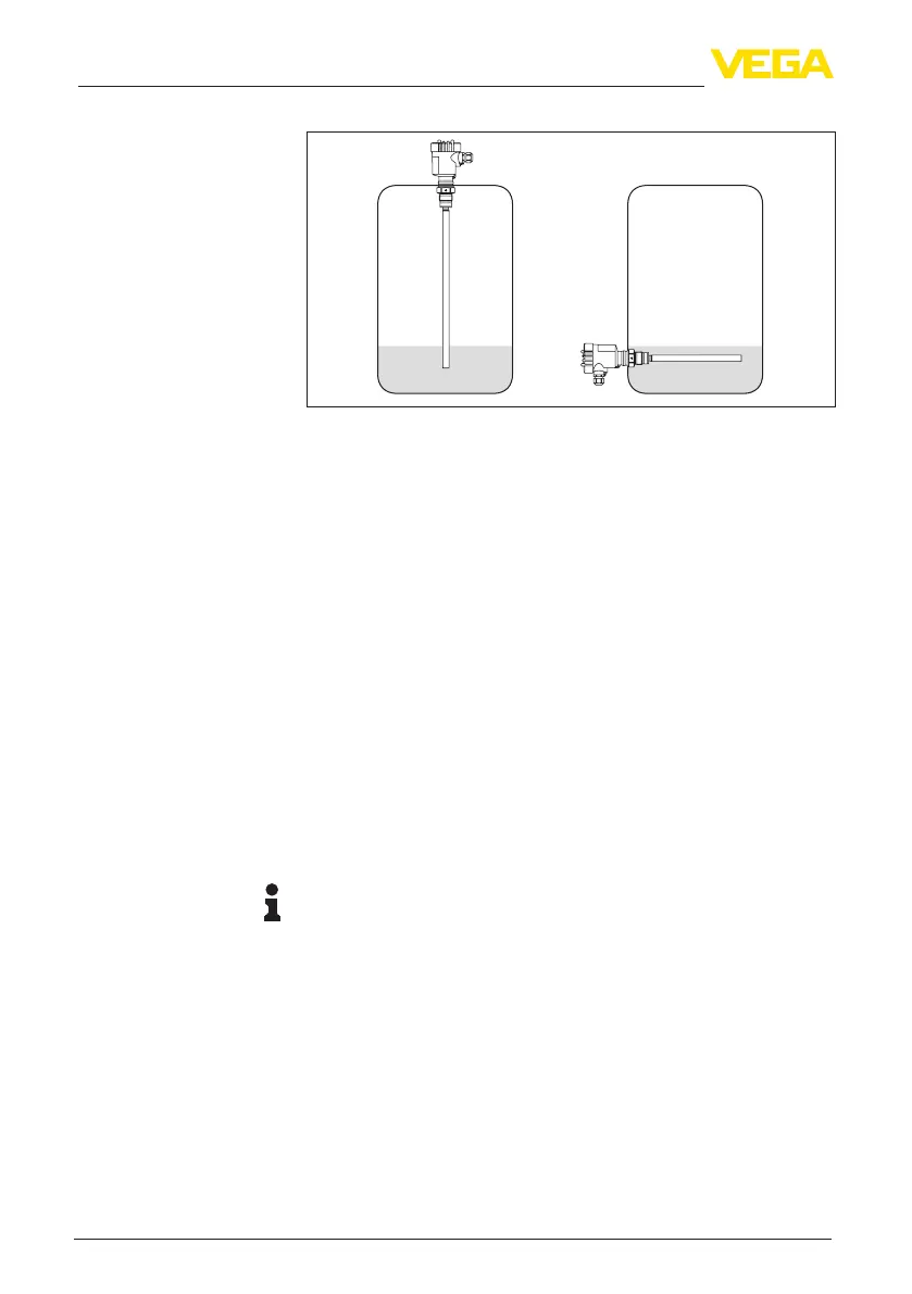
Fig. 7: Application examples of dry run protection with a capacitive point level
sensor
1. Makesurethatswitch1ontheDILswitchblockissetto"min.".
Theswitchesfortheswitch-onandswitch-odelayshouldbeset
to"0 s".
2. The vessel should be empty i.e. the sensor must not be covered
3. Set the potentiometer to the left end position, the yellow LED
display lights
4. Turn the potentiometer slowly clockwise until the yellow LED
display extinguishes, note the position of the potentiometer
5. Continuellingthevesseluntilthesensoriscompletelycovered,
the yellow LED display lights
6. Turn the potentiometer slowly clockwise until the yellow LED dis-
play extinguishes again, note also this position of the potentiom-
eter
7. Calculate the average value from these two values and set it on
the potentiometer, the controller is then ready for operation
6.5 Proof test
Note:
Whenhandlingenvironmentallyhazardoussubstances,dangertothe
environment and to persons must be avoided. After setup, the proper
functioning of the instrument must be ensured by means of the proof
test described below.
•
Detection of line break: Disconnect the sensor cable for the
duration of this test
– The red fault LED must light up
– Therelaymustbedeenergized
•
Detection of short-circuit: Short-circuit the sensor cable for the
duration of this test
– The red fault LED must light up
– Therelaymustbedeenergized
Dry run protection (min.
operation)

 Loading...