8 Chapter 2 Installation Instruction
NetSure 531 A41, NetSure 531 A91 Subrack Power system User Manual
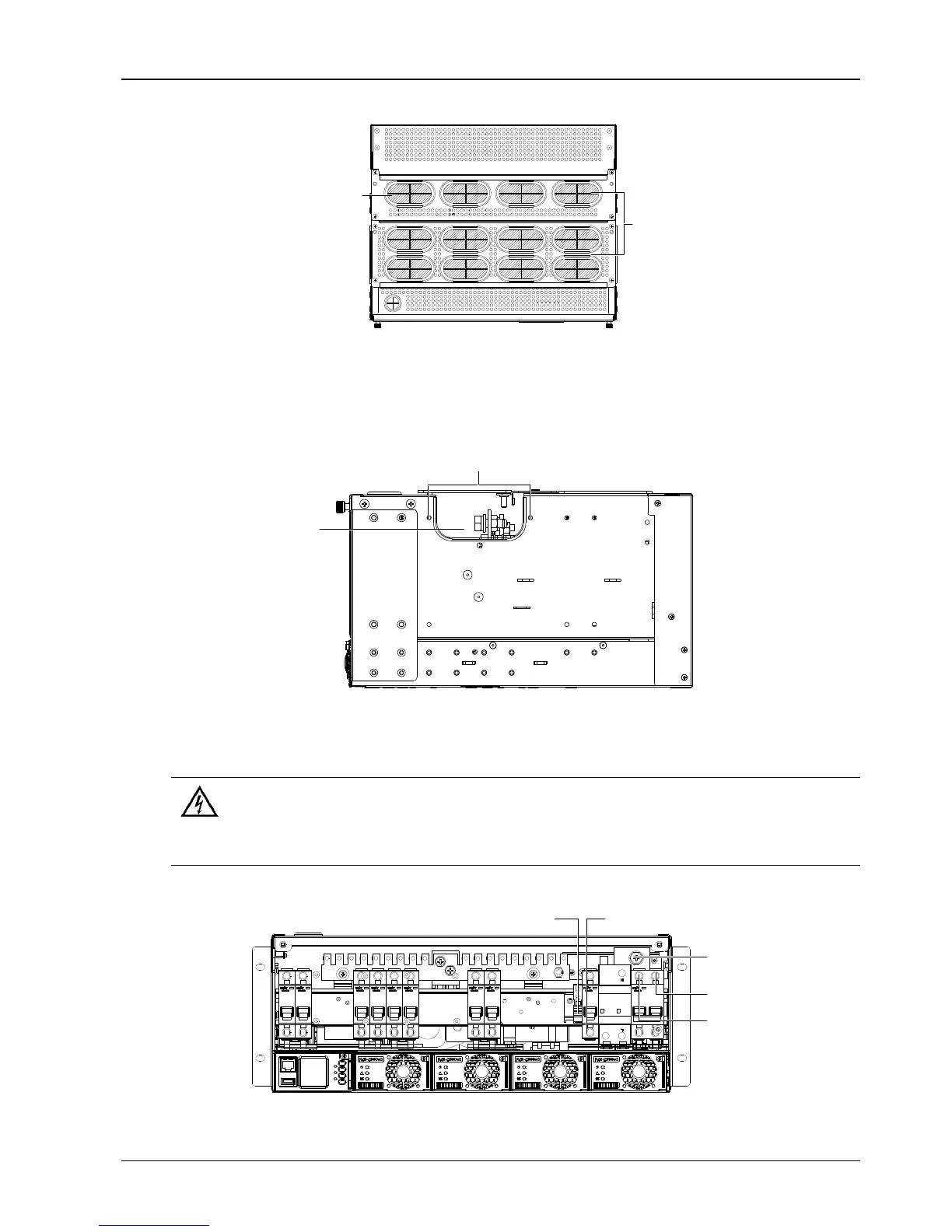
Rubber ring top cover for MFU unit cabling is shown in Figure 2-8.
Cable outlet area
Latex unit
Figure 2-8 Cable entry Illustration of the MFU unit
Dismantle several square units of the cable outlet area on site according to the actual cable outlet space.
Cabling from side of the power system
Use a cross head screwdriver to remove two screws which fix the cabling panel at side of cabling area, then the cable
can be led out from the cabling area, as shown in Figure 2-9.
Screw
Cable-bundling plate
(cabling area)
Figure 2-9 Side cable cabling Illustration
2.4.2 Connecting AC Input Cables
1. Switch off all MCBs before the electrical connection.
2. Only the qualified personnel can do the mains cable connection.
Take the NetSure 531 A41 power system as an example, the positions of the terminals are shown in Figure 2-10.
AC output terminal N AC output terminal L
AC input terminal N
AC input terminal L
Figure 2-10 Illustration of the connection terminal

 Loading...


